Thevenin’s Theorem is very useful particularly when the current in one branch of a network is to be determined.
Statement of Thevenin’s Theorem
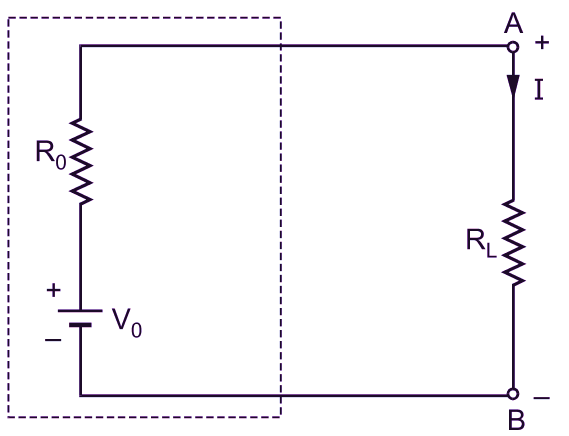
Thevenin's Theorem states that for the purpose of determining the current through a resistor RL (called load resistance) connected across any two terminals A and B of a linear bilateral network with constant resistances, and constant voltage and current sources (Fig. 1 a), the network excluding RL (enclosed by dotted line in Fig. 1 a), can be replaced by a single source of e.m.f. and a series resistor (enclosed by dotted line in Fig. 1 b) where

(i) this e.m.f is equal to the open-circuit voltage, say Vo, between the terminals under consideration (i.e. the voltage across the two terminals A and B with RL removed) and,

(ii) the resistance of the series resistor, say Ro, is equal to the resistance of the network as viewed from the terminals A and B with the load resistance RL removed amid all sources replaced by their internal resistances.
Hence, the current through RL,
\[\text{I }=\text{ }\frac{{{\text{V}}_{\text{o}}}}{{{\text{R}}_{\text{o}}}+{{\text{R}}_{\text{L}}}}\]
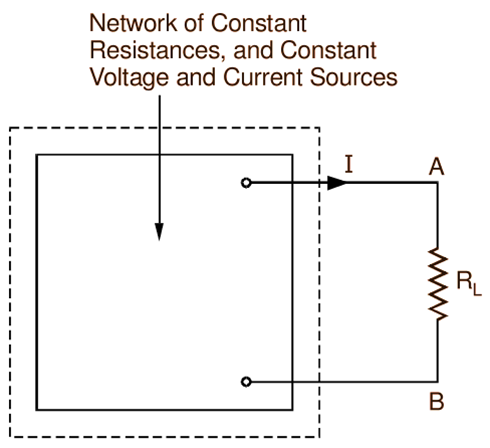
(a)
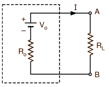
(b)
Fig. 1: General two-terminal network with Thevenin’s equivalent circuit.
Thevenin’s Theorem Formula
Current through the load resistance connected across any two terminals A and B of a linear bilateral network with constant resistances, constant voltage and current sources,
\[\text{I }=\text{ }\frac{{{\text{V}}_{\text{o}}}}{{{\text{R}}_{\text{o}}}+{{\text{R}}_{\text{L}}}}\]
where
RL = Load resistance connected across the terminals A and B.
V0 = Thevenin’s equivalent voltage i.e. the open-circuit voltage between the terminals A and B with the load resistance RL removed.
R0 = Thevenin’s equivalent resistance i.e. the resistance of the network as viewed from the terminals A and B with the load resistance RL removed and all sources replaced by their internal resistances.
Explanation of Thevenin’s Theorem
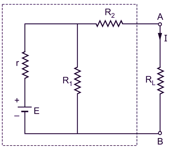
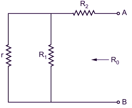
To understand the application of the above theorem more clearly, let us consider the network shown in Fig. 2 (a). It consists of resistors R1, R2, and RL, and a battery having an e.m.f. E and an internal resistance r. If it is required to find the current through a load resistance RL using Thevenin’s theorem, the procedural steps are as follows:
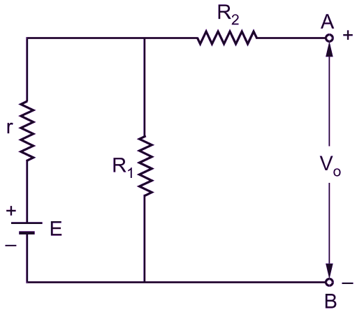
(i) Remove the load resistance RL from the terminals A and B and find the open-circuit voltage V0 between these terminals. Referring to Fig. 2 (b), it is obvious that
\[\text{Current through }{{\text{R}}_{\text{1}}}=\text{ }\frac{\text{E}}{{{\text{R}}_{\text{1}}}+\text{r}}\]
and
\[\text{p}\text{.d across }{{\text{R}}_{\text{1}}}=\text{ }\frac{\text{E }{{\text{R}}_{\text{1}}}}{{{\text{R}}_{\text{1}}}+\text{r}}\]
Since, no current is flowing through R2, open-circuit voltage across the terminals A and B is
\[{{\text{V}}_{\text{o}}}=\text{ }\frac{\text{E }{{\text{R}}_{\text{1}}}}{{{\text{R}}_{\text{1}}}+\text{r}}\]
(a)
(b)
(c)
(d)
Fig. 2: Circuits to illustrate Thevenin’s theorem
(ii) With the load resistance RL removed and the battery replaced by its internal resistance r as shown in Fig. 2 (c), find the Thevenin’s equivalent resistance R0 of the network as viewed from the terminals A and B. Obviously,
\[{{\text{R}}_{\text{o}}}=\text{ }{{\text{R}}_{\text{2}}}+\text{ }\frac{\text{r }{{\text{R}}_{\text{1}}}}{{{\text{R}}_{\text{1}}}+\text{r}}\]
(iii) Replace the entire network enclosed by the dotted line in Fig. 2 (a) by the Thevenin’s equivalent circuit consisting of single voltage source with e.m.f. equal to V0 and internal resistance equal to R0 as illustrated in Fig. 2 (d).
(iv) Finally, from the simple circuit of Fig. 2 (d), calculate the current I flowing through the load resistance RL using the expression
\[\text{I }=\text{ }\frac{{{\text{V}}_{\text{o}}}}{{{\text{R}}_{\text{1}}}+{{\text{R}}_{\text{L}}}}\]
Examples of Thevenin’s Theorem
Example 1 : Using Thevenin’s theorem, calculate the current in the 15 Ω resistor in the network shown in Fig. 3.
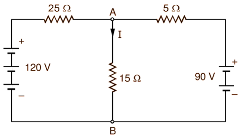
Fig. 4.
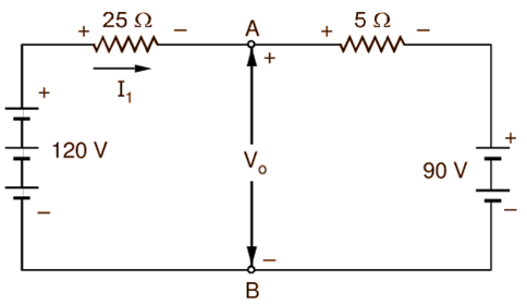
Solution 1: For convenience, the network under consideration is redrawn in Fig. 3. Open circuiting the branch containing 15 Ω resistor gives the network shown in Fig. 4 (a). To calculate the open-circuit voltage V0 across the terminals A and B, assume a current I1 in the direction shown. Applying the Kirchhoff’s voltage law to the outer loop, we get
120 – 25I1 – 5I1 – 90 = 0
∴ I1 = 1 A
(a)
(b)
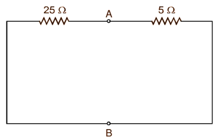
Fig. 4: (a) Network of Fig. 4 with the 15 resistor removed, (b) Network of Fig. 4 (a) with voltage sources suppressed.
From the voltage law, the open-circuit voltage across the terminals A and B is then
Vo = 120 – 25 × 1 = 95 V
To determine the Thevenin’s equivalent resistance Ro, the voltages of the sources are reduced to zero and the resistance between the terminals A and B is calculated. Fig. 4 (b) shows the network after the suppression of the voltage sources. The 25 Ω and 5 Ω resistances being in parallel between the terminals A and B,
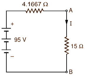
Fig. 5 : Thevenin’s equivalent of the circuit of Fig. 3.
The Thevenin’s equivalent circuit for the network of Fig. 4 (a) between the terminals A and B with 15 Ω resistance added is then as shown in Fig. 5. Hence, current through 15 Ω resistance is
\[\text{I }=\text{ }\frac{{{\text{V}}_{\text{o}}}}{{{\text{R}}_{\text{1}}}+{{\text{R}}_{\text{L}}}}\text{ }=\text{ }\frac{\text{95}}{\text{401667}+\text{15}}\]
\[=\text{ 4}\text{.9565 A}\]