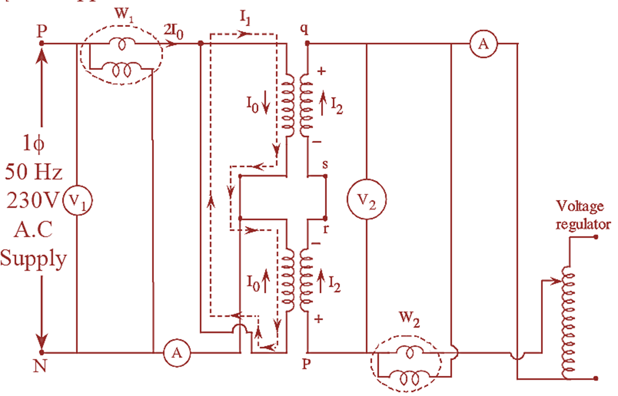
Figure 1: Sumpner’s Test (Back to Back Test) of Transformer.
Sumpner’s test is the improved method of determining the regulation, efficiency and heating on load conditions than O.C and S.C tests. This test requires two similar transformers, which can be connected to the supply in such a way that one is loaded on other. The power drawn from supply is necessary for supplying losses of the transformer and losses in circuit are negligible.
Figure 1 shows the circuit diagram for Sumpner’s test which is also called load test or back to back test. The circuit diagram consists of two identical transformers whose primaries and secondaries are connected to rated supply mains and voltage regulators respectively.
The circuit diagram also consists of measuring instruments (wattmeters, ammeters and voltmeters) in between supply mains and transformers primaries and also in between secondaries and voltage regulator.
The primaries are connected parallel to each other, but the secondaries are connected in series with their polarities in phase opposition.
Procedure for Sumpner’s Test (Back to Back Test) of Transformer
It should be confirmed that the polarities of the secondaries are in phase opposition. This is done by using the voltmeter V2 connected across terminal pq. When supply is given to the transformer primary by keeping the secondaries open, voltmeter V2 should indicate zero i.e., V = 0. This confirms that the series connected secondaries have their polarities in opposition.
Now, even if the terminals of pq are shorter the current in the secondary will be zero because voltage, Vpq = 0 and the reading in the wattmeter W1 remains unaltered.
By giving supply to the voltage regulator from a separate source or from the same source used for the primaries, voltage is injected in the secondary circuit.
This injected voltage is adjusted till rated current flows in the secondary windings (series connected). In the primary winding, the rated current is already flowing due to the transformer action. The rated current in the primary will not affect the wattmeter W1 as this current is flowing only in the primary’ windings shown with dotted lines in figure.
The voltage reading in the voltmeter V2 is noted down which gives the sum of leakage drops in both the transformers.
Because of the injected voltage, full-load current flows both in the primary and secondary windings as a result, the iron losses are obtained from the wattmeter reading as W1 = 2Pi and full-load copper losses are obtained from the wattmeter reading ‘W2‘ as W2 = 2Pcu.
Therefore, the efficiency of each transformer can now be calculated as,
\[\eta =\frac{\text{ Output }}{\text{Output}+\text{ Total losses}}\]
Where,
\[\text{Total losses = }{{P}_{i}}+{{P}_{cu}}\] \[=\frac{{{W}_{1}}}{2}+\frac{{{W}_{2}}}{2}\]
The transformers are kept under rated loss conditions for several hours till maximum stable temperature is reached and hence the temperature rise of the two transformers can be measured.