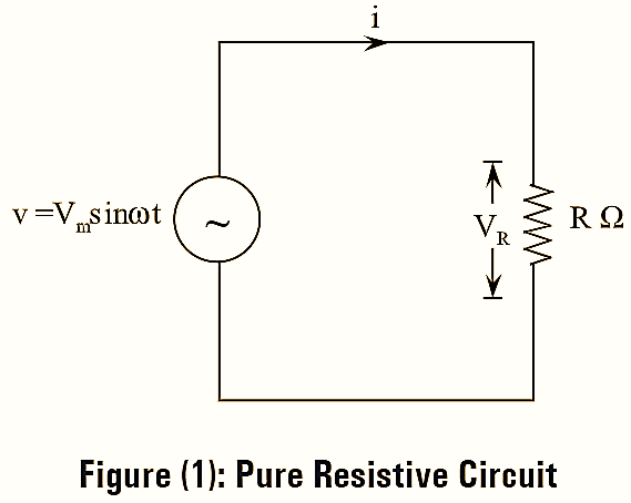
Purely Resistive Circuit having a pure resistor ‘R’ connected across an A.C voltage source as shown in figure (1). Let the voltage applied to circuit be v.

\[v={{V}_{m}}\sin \theta ={{V}_{m}}\sin \omega t\]
Due to the voltage applied an alternating current flows through the circuit. Let this instantaneous current be “i”.
Applying KVL to the above circuit, we have,
\[v=iR\] \[i=\frac{v}{R}\] \[i=\frac{{{V}_{m}}\sin \omega t}{R}\]
The value of “i” will be maximum when sinωt = 1
\[{{I}_{m}}=\frac{{{V}_{m}}}{R}\] Instantaneous current, i = Im sinωt
Phasor Diagram of Purely Resistive Circuit

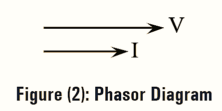
From the phasor diagram shown in figure (2), it is clear that the A.C voltage and current are in-phase i.e., there is no phase difference between them.
Impedance of Purely Resistive Circuit
The impedance ‘Z’ is given by the quantity \(\sqrt{{{R}^{2}}+{{X}^{2}}}\) which offers opposition to the current flow in the circuit and is measured in ohms (Ω).
\[I=\frac{V}{Z}=\frac{V}{\sqrt{{{R}^{2}}+{{X}^{2}}}}\]
Here the circuit consists of only resistive element.
The impedance of circuit,
\[Z=\sqrt{{{R}^{2}}}=R\Omega \]
Instantaneous Power of Purely Resistive Circuit
Instantaneous power, P = VI
Where,
\[v={{V}_{m}}\sin \omega t\]
\[i={{I}_{m}}\sin \omega t\]
\[P=\left( {{V}_{m}}\sin \omega t \right)\left( {{I}_{m}}\sin \omega t \right)\]
\[={{V}_{m}}{{I}_{m}}\sin \omega t\]
\[={{V}_{m}}{{I}_{m}}\left[ \frac{1-\cos 2\omega t}{2} \right]\text{ }\left[ {{\sin }^{2}}\omega t=\frac{1-\cos 2\omega t}{2} \right]\]
\[=\frac{{{V}_{m}}{{I}_{m}}}{2}-\frac{{{V}_{m}}{{I}_{m}}}{2}\cos 2\omega t\]
Instantaneous power consists of two parts,
- \(\left( \frac{{{V}_{m}}{{I}_{m}}}{2} \right)\) represents steady power
- \(\left( \frac{{{V}_{m}}{{I}_{m}}}{2}\cos 2\omega t \right)\) represents fluctuating power.
Average Power of Purely Resistive Circuit

\[{{P}_{avg}}=\frac{1}{2\pi }\int\limits_{0}^{2\pi }{\frac{{{V}_{m}}{{I}_{m}}}{2}d\left( \omega t \right)}+\frac{1}{2\pi }\int\limits_{0}^{2\pi }{\frac{{{V}_{m}}{{I}_{m}}}{2}\cos 2\omega t.d\left( \omega t \right)}\]
\[=\frac{1}{2\pi }\left[ \frac{{{V}_{m}}{{I}_{m}}}{2} \right]\left( \omega t \right)_{0}^{2\pi }+\frac{1}{2\pi }\frac{{{V}_{m}}{{I}_{m}}}{2}\int\limits_{0}^{2\pi }{\cos 2\omega t.d\left( \omega t \right)}\]
\[=\frac{1}{2\pi }\frac{{{V}_{m}}{{I}_{m}}}{2}\left[ 2\pi -0 \right]+\frac{1}{2\pi }\left( \frac{{{V}_{m}}{{I}_{m}}}{2}\left[ \frac{\sin \omega t}{2} \right]_{0}^{2\pi } \right)\]
\[=\frac{{{V}_{m}}{{I}_{m}}}{2}+\frac{1}{2\pi }\left[ \frac{{{V}_{m}}{{I}_{m}}}{4}\left[ 0-0 \right] \right]\]
\[=\frac{{{V}_{m}}{{I}_{m}}}{2}+0\]
Total average power
\[{{P}_{avg}}=\frac{{{V}_{m}}{{I}_{m}}}{2}\]
\[=\frac{{{V}_{m}}}{\sqrt{2}}\times \frac{{{I}_{m}}}{\sqrt{2}}=VI\text{ watts}\]
Power Factor of Purely Resistive Circuit
It is defined as the cosine of the phase angle between current and voltage.
Power factor = cosϕ
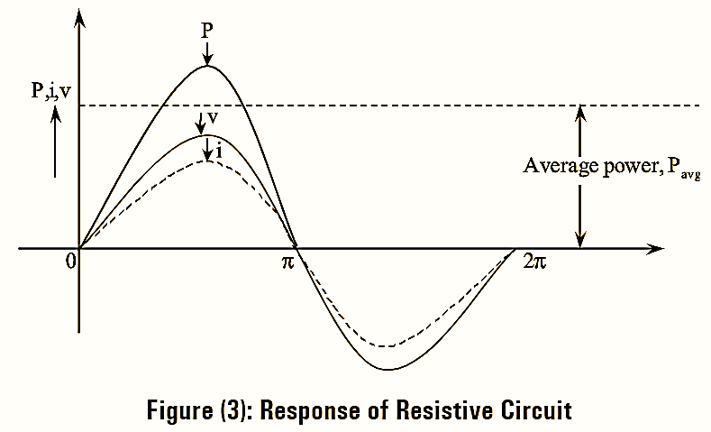
The voltage and current pass through their zero values at same instant and attain their positive and negative peaks at the same instant as shown in figure (3). Therefore, the phase difference between voltage and current is zero i.e ϕ = 0.
The power factor, cosϕ = 1.
Power factor for resistive circuit is unity.