Purely Inductive Circuit having a pure inductance ‘L’ connected across an A.C voltage source as shown in figure (1). Let the voltage applied to circuit be ‘v’.
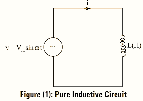
\[v={{V}_{m}}\sin \omega t….(1)\]
Due to applied voltage an alternating current flows through the inductor and sets up a self-induced e.m.f ‘e’ of di magnitude \(L\frac{di}{dt}\). At every instant the applied voltage has to dt overcome this self-induced e.m.f.
Thus,
Applied alternating voltage = – (Self-induced e.m.t)
\[v=-e\]
\[v=L\frac{di}{dt}\] \[{{V}_{m}}\sin \omega t=L\frac{di}{dt}\]
\[di=\frac{{{V}_{m}}}{L}\sin \omega t\]
Integrating on both sides, we have,
\[\int{di}=\int{\frac{{{V}_{m}}}{L}\sin \omega t}\]
\[i=\frac{{{V}_{m}}}{L}\left( \frac{-\cos \omega t}{\omega } \right)\]
\[=\left( \frac{{{V}_{m}}}{L} \right)\sin \left( \omega t-90{}^\circ \right)….(2)\]
The value of ‘i’ will be maximum when sin (ωt – 90º) unity.
\[{{I}_{m}}=\frac{{{V}_{m}}}{\omega L}\] Substituting Im value in equation (2), we get,
Instantaneous current, i = Im sin (ωt – 90º)
Phasor Diagram of Purely Inductive Circuit
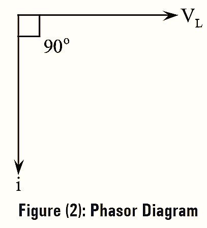
The phasor diagram of a Purely inductive circuit is shown in figure (2). From figure (2) it is clear that the current in the circuit lag behind the voltage by 90º.
Impedance of Purely Inductive Circuit
Impedance ‘Z’ of any circuit is given by,
\[Z=\sqrt{{{R}^{2}}+{{X}^{2}}}\]
Where,
R = Resistance of the circuit
X = Reactance of the circuit.
Here the circuit consists of only inductive element.
The impedance,
Z = XL
Where,
XL = Inductive reactance
XL = ωL = 2πfL
Inductive reactance is measured in ohms (Ω).
Instantaneous Power of Purely Inductive Circuit
\[P=Vi\] \[=\left( {{V}_{m}}\sin \omega t \right)\left( {{I}_{m}}\sin \left( \omega t-90{}^\circ \right) \right)\]
\[={{V}_{m}}{{I}_{m}}\sin \omega t\left( -\cos \omega t \right)\] \[=-{{V}_{m}}{{I}_{m}}\sin \omega t\cos \omega t\]
\[=\frac{-{{V}_{m}}{{I}_{m}}}{2}\sin 2\omega t\text{ }\left[ \sin 2\omega t=2\sin \omega t\cos \omega t \right]\]
Average Power of Purely Inductive Circuit
It is the total power over one full cycle.
\[{{P}_{avg}}=\frac{1}{2\pi }\int\limits_{0}^{2\pi }{-}\left( \frac{{{V}_{m}}{{I}_{m}}}{2} \right)\sin \omega td\left( \omega t \right)\]
\[=\frac{1}{2\pi }\left[ -\frac{{{V}_{m}}{{I}_{m}}}{2} \right]\int\limits_{0}^{2\pi }{\sin 2\omega td\omega t}\]
\[=\frac{-{{V}_{m}}{{I}_{m}}}{4\pi }\left[ \frac{-\cos \omega t}{2} \right]_{0}^{2\pi }\] \[=\frac{{{V}_{m}}{{I}_{m}}}{8\pi }\left[ 1-1 \right]=0\]
Therefore, the average power consumed by the circuit is zero.
Power Factor of Purely Inductive Circuit
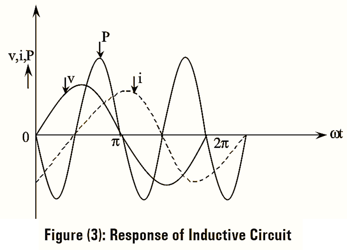
The phase difference between voltage and current is 90º with the current lagging i.e., the current waveform crosses its zero after the voltage waveform cross 90º as shown in figure (3).
ϕ = 90º lag
Power factor, cosϕ = 0