
Figure 1: PMMC Instrument.
Working Principle of PMMC Instrument
When a current carrying conductor is placed in a magnetic field the force is produced on the conductor (coil). This force tends to move the coil in the space.
Construction of PMMC Instrument
Fig. 1 shows constructional details of PMMC instruments with different constructions of permanent magnets. A coil is wound on aluminium former which is supported by spindle, the two ends of spindle are supported by Jewel bearings. Iron cylinder is placed inside the coil and this assembly is surrounded by permanent magnet coil carries current to be measured. The current is fed into and taken into from coil from springs, flexible ligaments are provided to make provision for this connection. Deflecting torque is produced as described in the working principle. Controlling torque is achieved with springs and damping torque is provided with the help of aluminium former. The iron cylinder (core) minimizes fringing effect and concentrates the flux in the region near coil sides. The iron cylinder makes the orientation of magnetic field radial. Deflection is observed at the pointer dial. The defecting torque (Td) is directly proportional to current hence scale is uniform.
PMMC Instrument Parts, Material and their Functions
| Name of part | Material | Function |
| Permanent magnet | Ferromagnetic | To produce magnetic flux |
| Iron cylinder | Magnetic | To strengthen magnetic flux linkage |
| Coil | Copper | To carry current and produce deflection |
| Former | Aluminium | To support coil and to produce damping torque. |
| Spindle | Steel | To support the coil and to provide means for rotation. |
| Flexible ligament | Thin steel strips | To provide connection between meter terminal and coil. |
| Spring | Phospher bronze | To provide leads for incoming and outgoing connection to coil, To produce controlling torque. |
| Pointer | Aluminium | To show reading on calibrated scale. |
Suitability of PMMC Instrument
This instrument is suitable for DC measurements only. If it is connected to ac supply the direction of alternating torque alters every half cycle and moving system cannot cop up with such rapid variations. So pointer stays at zero position.
Advantages of PMMC Instrument
- Deflection is proportional to current,
\[{{T}_{d}}\propto l\]
Therefore scale is uniformly divided.
- Power consumption is very low.
- High accuracy due to high torque to weight ratio.
- Sensitivity is high because of strong magnetic flux. Errors due to stray magnetic field are small because operating magnetic field is strong.
- It is free from hysteresis and stray magnetic field errors.
- Uses effective damping method. (eddy current damping)
- Single instrument can be used for different current and voltage ranges using shunt and multiplier.
- Torque to weight ratio of moving system is high.
Disadvantages of PMMC Instrument
- Suitable for DC measurements only.
- Cost is higher than moving iron instrument.
- Strength of permanent magnet decreases due to ageing.
- Delicate construction, so to be used with care.
- Thermo-electric EMF may cause errors when it is used with shunts. 2.3.1(C)
Derivation of Torque Equation of PMMC Instrument
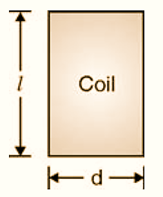
l – Length of the coil in meters
B — Flux density in air gap in Tesla
d – Width of coil in meters
i – Current through moving coil in Amp
k – Spring constant in Nm/rad
θ – Final state deflection in rad
α – Angle between direction of magnetic field and velocity vector of moving coil for radial field.
Expression for force on each coil side given by,
\[=N\text{ }Bi\text{ }l\text{ sin }\alpha \]
Due to radial flux the coil cuts flux at 90º always
\[\alpha =90{}^\circ \] \[\text{Force = }N\text{ }Bi\text{ }l\text{ }……..\text{since }\alpha =90{}^\circ \]
Deflecting torque
\[{{T}_{d}}=\left( N\text{ }Bi\text{ }l \right)\times \left( d \right)=N\text{ Bi A }…\left( A=l\times d \right)\]
N, B, A are constants in instrument
\[{{T}_{d}}=N\text{ B Ai = Gi}\]
Where,
G = NBA known as displacement constant
Controlling torque is provided by means of spring,
\[{{T}_{c}}=k\theta \]
Where k is spring constant unit : Nm / rad
\[\theta =\text{ Final steady deflection in rad}\text{.}\]
At final steady deflection
\[{{T}_{c}}={{T}_{d}}\text{ } k\theta \text{ }=\text{ }Gi\] \[\theta =\frac{Gi}{k}\]
Thus deflection is proportional to i that is why scale is uniform.