Transformer, being a stationary electrical equipment, does not have rotational or windage losses. The losses which occur in a transformer are,
- Copper losses
- Iron or core losses.
1. Copper Losses
These losses occur due to the resistance of the transformer windings and appear as heat resulting in the increase of temperature. If R1 and R2 are the primary and secondary; resistances and I1 and I2 are the primary and secondary’ currents, then the copper loss in the respective windings is given by,
\[\text{Copper loss in primary = I}_{1}^{2}{{R}_{1}}\text{ and}\]
\[\text{Copper loss in secondary = I}_{2}^{2}{{R}_{2}}\]
\[\text{Total copper loss = ( I}_{1}^{2}{{R}_{1}}\text{ }+\text{ I}_{2}^{2}{{R}_{2}}\text{ )}\]
\[\text{Copper losses at load = }{{\left( \frac{1}{2} \right)}^{2}}{{P}_{c}}\]
These losses depend on transformer load. Copper losses at various loads can be determined as follows,
\[\text{Copper losses at load = }{{\left( \frac{1}{2} \right)}^{2}}{{P}_{c}}\]
\[\text{Copper losses at }{{\frac{1}{4}}^{th}}\text{ of full load = }{{\left( \frac{1}{4} \right)}^{2}}{{P}_{c}}\]
Where,
Pc is the copper loss at full-load.
2. Iron or core losses
Iron (or) core losses occur when the core is subjected to alternating flux. These losses are further divided into two types, namely,
- Hysteresis loss and
- Eddy current loss.
1. Hysteresis Loss
Hysteresis loss occurs due to the continuous magnetization and demagnetization of the core. In every cycle of alternating flux, i.e., magnetization, the hysteresis loss appears as heat. Hysteresis loss exists by virtue of property of material.
Hysteresis loss is given by the relation,
\[{{P}_{h}}={{K}_{v}}VfB_{\max }^{x}\text{ watts}\]
Where,
Kh = Constant
f = Frequency
V = Volume of magnetic core
Bmax = Maximum value of flux density
x = Value of x that varies from 1.5-2.0.
Hysteresis losses cannot be eliminated. However, they can be minimized by selecting the core material which posses low hysteresis coefficient. For example, silicon steel and nickel-iron alloys.
2. Eddy Current Loss
Alternating flux linking with the core induces an e.m.f in it and causes circulating current known as eddy current to flow within the body of the transformer core. These eddy currents lead to the power loss given by I2R and are also called as eddy-current losses. These losses depend upon the length of the eddy current path and the effective resistance.
Eddy current losses are given by the relation,
\[{{P}_{e}}={{K}_{e}}{{f}^{2}}B_{\max }^{2}\text{ V}{{\text{t}}^{2}}\text{ watts}\]
Where,
Ke = Constant
f = Frequency
Bmax = Maximum value of flux density
V = Volume of the core
t = Thickness of the lamination.
Similar to the hysteresis losses, it is impossible to eliminate eddy-current losses. However, they can be reduced by using laminations of thickness suitable to the capacity of the machine. Using laminations, effective resistance to the eddy currents can be increased and length of the circulating current path is decreased, thereby reducing the eddy current losses.
In transformers, iron or core losses play a vital role in deciding the equipment rating, temperature rise and efficiency.
Basically the transformers receive the power at one voltage and deliver at another voltage. Both the input and output are electrical. The presence of iron core, reactance and winding contributes some losses which are due to alternating magnetisation of the core, leakage reactance and the power wasted in copper portion of windings.
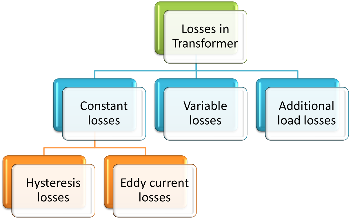
The losses are of three types:
- Constant losses.
- Variable losses.
- Additional load losses
Constant losses
These are independent of load current. These includes the hysteresis and eddy current losses. As in case of a transformer, the core flux remains constant from no load to full load, so these losses remains constant from no load to full load. These losses are the hysteresis and eddy current losses.
The hysteresis losses are related to the area of B.H. loop of the material used. The losses in a given time is proportional to the number of times the loop travels. According to the steinmetz,
Hysteresis losses,
\[{{W}_{h}}\propto B_{m}^{1.6}f\]
Eddy current losses,
\[{{W}_{e}}\propto B_{m}^{2}f\]
The eddy current losses are also related with the thickness of the lamination. To minimise these losses the cores are made of laminations of silicone steel with the thickness ranging from 0.35 to 0.5 mm.
Variable losses
These are proportional to the load current. These are the copper losses. These are due to the resistance of the transformer windings. These losses are proportional to the square of the load current.
\[\text{Total copper loss}=I_{1}^{2}{{R}_{1}}+I_{2}^{2}{{R}_{2}}\]
Additional load losses
Apart from these losses, there are some additional losses. These are due to the induction of current in the parts of the transformer other than the cores such as tank, structural steel and even in copper winding. This happens only on load hence the name is given the additional load losses.
Methods for determining the iron and copper losses of a transformer
These are two methods for determining these losses:
- Open circuit test.
- Short circuit test.
Open circuit test
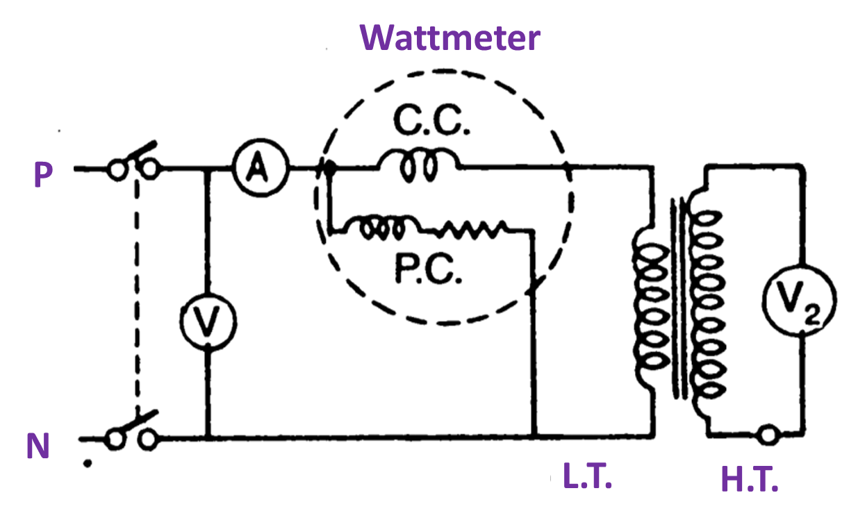
Fig. 2. Open circuit
This test is performed to find out the iron losses of the transformer. In this test one winding is connected to the supply of normal voltage and frequency. The circuit of the other winding is kept open. A wattmeter, ammeter, and voltmeter is connected to the supply side. In this test the H.T. winding is kept open circuited and L.T. is connected to the mains. It is because the metering is easy on low tension side.
Under these circumstances the flux will be produced in the core and it is obvious that the magnitude of the flux under the full load condition or on no load condition remains the same. So all the parts and cores of the transformer are under going to the same magnetic stresses.
As shown in Fig. 2 the connected wattmeter indicates the no load power losses or the iron losses. The ammeter indicates the no load current of the transformer. These losses remains constant from no load to full load, from the datas obtained by this test, the R0, X0, cos Φ0 and I0 , Iω , Iμ and the transformation ratio can be determined.
Short circuit test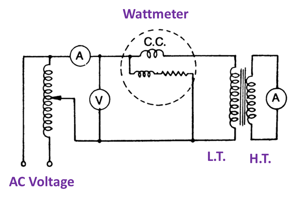
Fig. 3. Short circuit test.
This test is performed to determine the copper losses at any desired load. In this test the low voltage side is short circuited through an ammeter or by simply a thick copper conductor. The ammeter on primary and secondary side are suitably selected according to the capacity of the transformer. A low voltage is applied usually 5 to 10% of the normal primary voltage with the help of a variable transformer as shown in Fig. 3. The voltage help of a variable transformer as shown in Fig. 3. The voltage is so adjusted as to have desired load current through the windings. Since the applied voltage is small enough so the flux is also reduced that of the normal value. Hence the core losses are negligible and the total reading obtained from the wattmeter is the copper losses of the transformer at that particular load.
In this test generally the low voltage side is short circuited, because metering on low side will be unusual because of much current in L.T. side than H.T. The copper losses are proportional to the square of current.
From this test the equivalent impedance, Z01 referred to respective winding and the equivalent reactance also can be calculated. The current transformation ratio can also be verified.