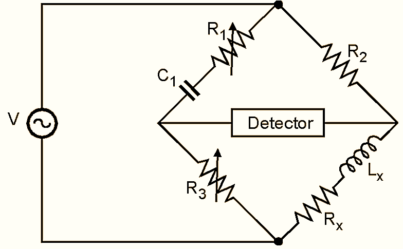
Hay’s Bridge method of measurement is particularly suited for the measurement of inductance having high Q Values.

Figure 1: Hay’s Bridge.
The schematic of Hay’s bridge is shown in Fig. 1. Hay’s bridge differs from Maxwell’s bridge by having a resistance R1 in series with a capacitor Cl instead of being parallel.
For large phase angles, R1 needs to be low; therefore this bridge is more convenient for measuring high Q coils. For Q =10, the error is ± 1% and for Q = 30, the error is ± 0.1%.
When bridge is balanced,
\[{{Z}_{1}}{{Z}_{x}}=\text{ }{{Z}_{2}}{{Z}_{3}}\text{ }……\left( 1 \right)\]
\[{{Z}_{1}}={{R}_{1}}-\frac{j}{\omega {{C}_{1}}}\]
\[{{Z}_{2}}={{R}_{2}}\]
\[{{Z}_{3}}={{R}_{3}}\]
\[{{Z}_{x}}={{R}_{x}}+j\omega {{L}_{x}}\]
From equation (1),
\[\left( {{R}_{1}}-\frac{j}{\omega {{C}_{1}}} \right)\left( {{R}_{x}}+j\omega {{L}_{x}} \right)={{R}_{2}}{{R}_{3}}\]
\[{{R}_{1}}{{R}_{x}}+j\omega {{L}_{x}}{{R}_{x}}-\frac{j{{R}_{x}}}{\omega {{C}_{1}}}+\frac{{{L}_{x}}}{{{C}_{1}}}={{R}_{2}}{{R}_{3}}\]
\[\left( {{R}_{1}}{{R}_{x}}+\frac{{{L}_{x}}}{{{C}_{1}}} \right)+j\left( \omega {{L}_{x}}{{R}_{1}}-\frac{{{R}_{x}}}{\omega {{C}_{1}}} \right)={{R}_{2}}{{R}_{3}}\]
Equation real and imaginary terms
\[{{R}_{1}}{{R}_{x}}+\frac{{{L}_{x}}}{{{C}_{1}}}={{R}_{2}}{{R}_{3}}\text{ }…\left( 2 \right)\]
\[\omega {{L}_{x}}{{R}_{1}}-\frac{{{R}_{x}}}{\omega {{C}_{1}}}=0…\left( 3 \right)\]
Thus,
\[{{L}_{x}}=\frac{{{R}_{x}}}{{{\omega }^{2}}{{R}_{1}}{{C}_{1}}}\]
Substituting Equation (3) in equation (2)
\[{{R}_{1}}{{R}_{x}}+\frac{{{R}_{x}}}{{{\omega }^{2}}{{R}_{1}}C_{1}^{2}}={{R}_{2}}{{R}_{3}}\]
\[{{R}_{x}}\left[ {{R}_{1}}+\frac{1}{{{\omega }^{2}}{{R}_{1}}C_{1}^{2}} \right]={{R}_{2}}{{R}_{3}}\]
\[{{R}_{x}}\left[ \frac{{{\omega }^{2}}R_{1}^{2}C_{1}^{2}+1}{{{\omega }^{2}}{{R}_{1}}C_{1}^{2}} \right]={{R}_{2}}{{R}_{3}}\]
\[{{R}_{x}}=\frac{{{\omega }^{2}}C_{1}^{2}{{R}_{1}}{{R}_{2}}{{R}_{3}}}{1+{{\omega }^{2}}R_{1}^{2}C_{1}^{2}}…\left( 4 \right)\]
Substitution Equation (4) in equation (3)
\[{{L}_{x}}=\frac{{{\omega }^{2}}C_{1}^{2}{{R}_{1}}{{R}_{2}}{{R}_{3}}\text{ }}{\left( 1+{{\omega }^{2}}C_{1}^{2}R_{1}^{2} \right)\left( {{\omega }^{2}}{{C}_{1}}{{R}_{1}} \right)}\]
\[{{L}_{x}}=\frac{{{C}_{1}}{{R}_{2}}{{R}_{3}}\text{ }}{\left( 1+{{\omega }^{2}}C_{1}^{2}R_{1}^{2} \right)}…\left( 5 \right)\]
From Equation (5) unknown inductance can be calculated.
As ω appears in the expression for Lx, this bridge is frequency sensitive.
Quality factor (Q) for capacitor is
\[\omega {{L}_{x}}{{R}_{1}}-\frac{{{R}_{x}}}{\omega {{C}_{1}}}=0\text{ }\]
∴\[\text{ }\omega {{C}_{1}}{{R}_{1}}=\frac{1}{Q}\text{ }….\left( 6 \right)\]
Substituting Equation (6) in Equation (5)
\[{{L}_{x}}=\frac{{{C}_{1}}{{R}_{1}}{{R}_{3}}}{1+\frac{1}{{{Q}^{2}}}}\]
For a value of Q greater than 10, the term 1/Q2 will be smaller than 1/100 and therefore can be neglected.
Lx = C1R2R3 (for Q >10)
Thus for Q > 10, the equation obtained for Lx in Hay’s bridge is same as that in Maxwell’s bridge.
For inductors with Q less than 10, the 1/Q2 term can not be neglected. Hence this bridge is not suited for measurement of inductors having Q less than 10.
For measuring inductance using Hay’s bridge, unknown inductance is connected in one of the arms of Hay’s bridge and resistors R1 and R3 are adjusted to obtain balance of the bridge. Then using the Equation (5), unknown inductance can be calculated.
Advantages of Hay’s Bridge
- It can measure inductances with high Q i.e. Q > 10.
- A commercial bridge measures inductance from 1 μH to 100 H with ± 2% error.
- It can be used for measuring incremental inductance.
Disadvantages of Hay’s Bridge
- The unknown value of inductance depends on loss of inductor (Q) and also on operating frequency.
- It can not measure inductance with low Q i.e. Q < 10.