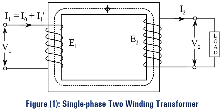
Consider the two winding single-phase transformer shown in figure (1).
\({{{I}}_{1}}\) = Current in the primary
\({{{E}}_{1}}\) = Induced e.m.f in the primary
\({{{V}}_{1}}\) = Voltage applied to the primary
\({{{I}}_{2}}\) = Current in the secondary
\({{{E}}_{2}}\) = Induced e.m.f in the secondary
\({{{V}}_{2}}\) = Terminal voltage of secondary
Here, the primary current \({{{I}}_{1}}\) has two components, one is no-load primary current, \({{{I}}_{0}}\) and the other one is load component of primary current \({{{I}’}_{2}}\). The function of current \({{{I}’}_{2}}\) is to counter balance the secondary current \({{{I}}_{2}}\). The no-load primary current \({{{I}}_{0}}\) leads to the production of losses in the core while magnetizing the core of the transformer. The no- load primary current \({{{I}}_{0}}\) can be resolved into two components i.e., active (or) working component Iw and reactive (or) magnetizing component ‘Iµ‘. The working component ‘Iw’ of no-load current \({{{I}}_{0}}\) leads to the core loss, hence it can be represented by a resistance R0. The magnetizing current ‘Iµ‘ produces flux which induces e.m.f E1.
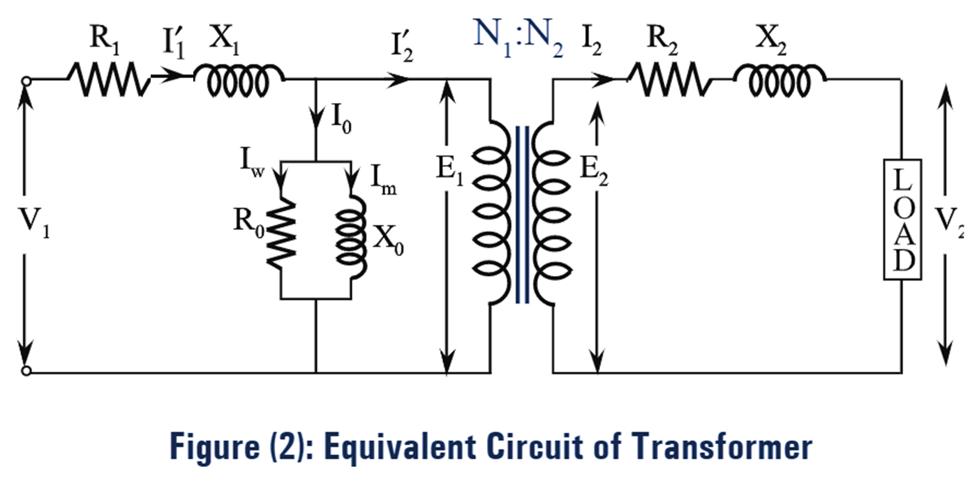
The reactance due to flux is represented by X0. To account for the core loss and the magnetizing current, an equivalent circuit can be represented by a shunt branch in the primary side as shown in the figure (2).
\[\text{Core loss = }I_{w}^{2}{{R}_{0}}=\frac{E_{1}^{2}}{{{R}_{0}}}\]
To make transformer calculations simpler, transfer voltage, current and impedance either to the primary or secondary
Equivalent Circuit of Transformer as Referred to Primary Side
Secondary parameters transferred to primary side are given as follows,
\[{{{R}’}_{2}}=\frac{{{R}_{2}}}{{{K}^{2}}}\]
\[{{{X}’}_{2}}=\frac{{{X}_{2}}}{{{K}^{2}}}\]
\[{{{Z}’}_{2}}=\frac{{{Z}_{2}}}{{{K}^{2}}}\]
\[{{{I}’}_{2}}=K{{I}_{2}}\]
\[{{{E}’}_{2}}=\frac{{{E}_{2}}}{K}\]
\[{{{V}’}_{2}}=\frac{{{V}_{2}}}{K}\]
Where,
\[K=\frac{{{N}_{2}}}{{{N}_{1}}}\]
We know that,
\[{{R}_{01}}={{R}_{1}}+{{{R}’}_{2}}={{R}_{1}}+\frac{{{R}_{2}}}{{{K}^{2}}}\]
\[{{X}_{01}}={{X}_{1}}+{{{X}’}_{2}}={{X}_{1}}+\frac{{{X}_{2}}}{{{K}^{2}}}\]
\[{{Z}_{01}}=\sqrt{R_{01}^{2}+X_{01}^{2}}=\frac{{{Z}_{02}}}{{{K}^{2}}}\]
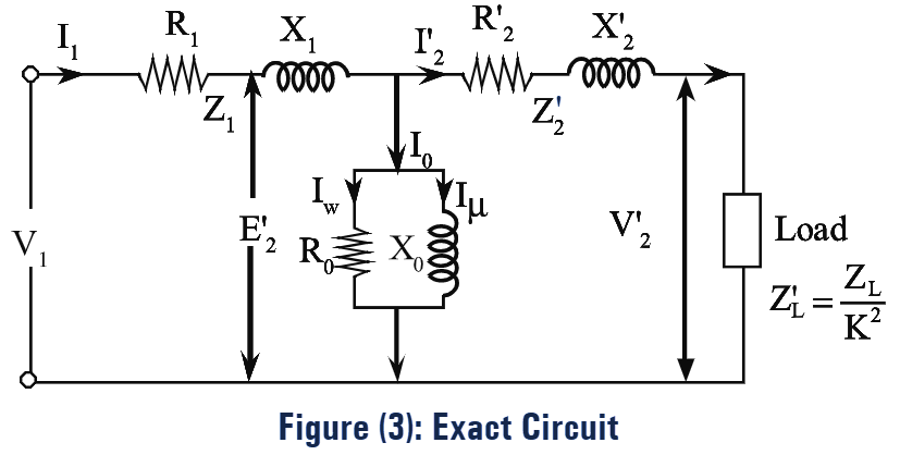
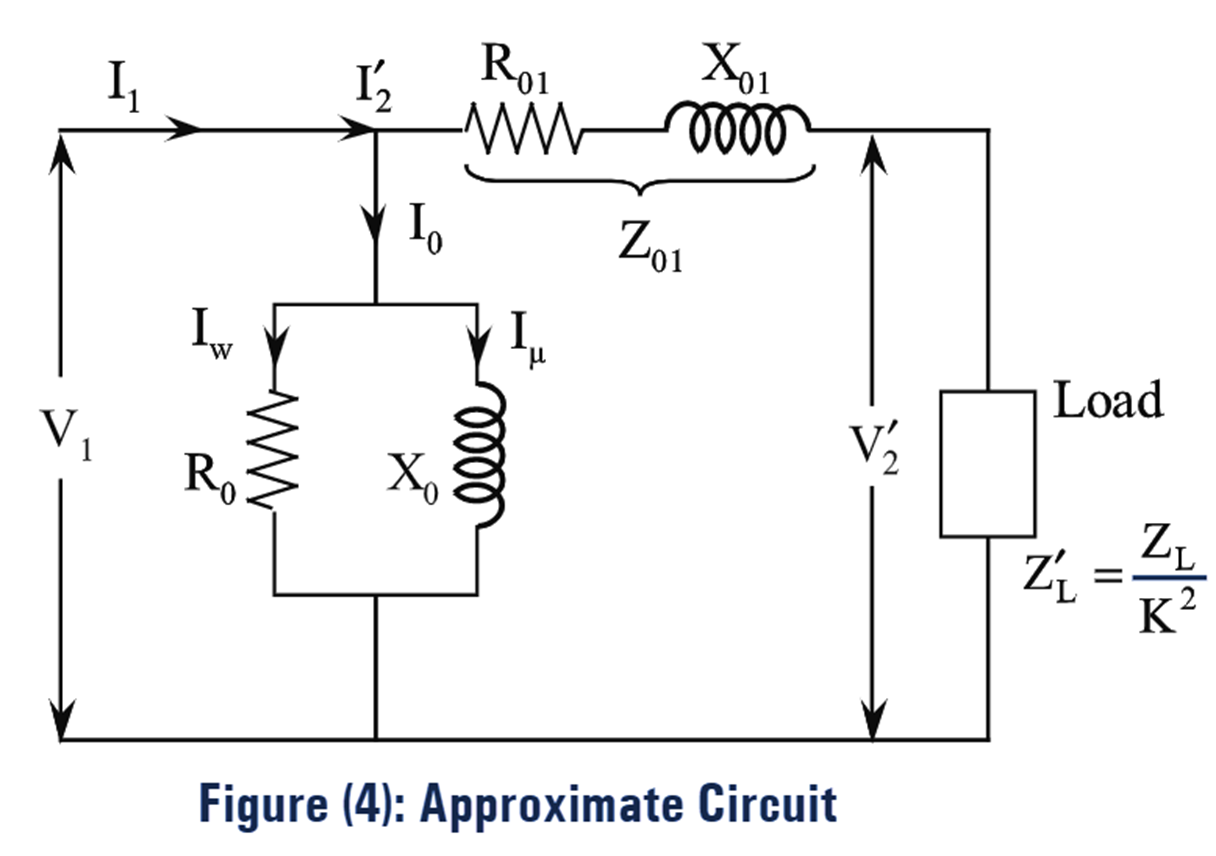
The equivalent circuits referred to primary side are as shown in figures (3) and (4).
Equivalent Circuit of Transformer Referred to Secondary Side
Primary parameters transferred to secondary side are given as follows,
\[{{{R}’}_{1}}={{K}^{2}}{{R}_{1}}\]
\[{{{X}’}_{2}}={{K}^{2}}{{X}_{1}}\]
\[{{{Z}’}_{1}}={{K}^{2}}{{Z}_{1}}\]
\[{{{E}’}_{1}}=K{{E}_{1}}\]
\[{{{V}’}_{1}}=K{{V}_{1}}\]
\[{{{I}’}_{1}}=\frac{{{I}_{1}}}{K}\]
\[{{{I}’}_{0}}=\frac{{{I}_{0}}}{K}\]
\[{{{R}’}_{0}}=\frac{{{R}_{0}}}{{{K}^{2}}}\]
\[{{{X}’}_{0}}=\frac{{{X}_{0}}}{{{K}^{2}}}\]
We know that,
\[{{R}_{02}}={{R}_{2}}+{{{R}’}_{2}}={{R}_{2}}+{{K}^{2}}{{R}_{1}}\]
\[{{X}_{02}}={{X}_{2}}+{{{X}’}_{1}}={{X}_{2}}+{{K}^{2}}{{X}_{1}}\]
\[{{Z}_{02}}=\sqrt{R_{02}^{2}+X_{02}^{2}}={{K}^{2}}{{Z}_{01}}\]
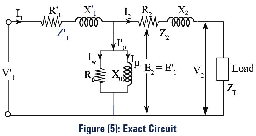
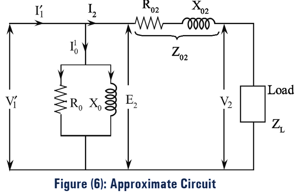
The equivalent circuit diagrams referred to secondary side are shown in figure (5) and figure (6).