Electrical Bus Bar is a conductor made up of copper or aluminium of larger cross-sectional area compared to the conventional conductors. It carries higher amount of currents in a limited space and to which all the incoming and outgoing feeders are connected in a substation.
The selection of a particular bus-bar arrangement is done depending upon the factors such as voltage level, simplicity, reliability, safety, cost of installation and maintenance, etc.
Bus-bar Arrangements
Different types of bus-bar arrangements available are,
- Single bus-bar system
- Single bus-bar with sectionalizer
- Main and transfer bus-bar system.
Single Bus-bar System

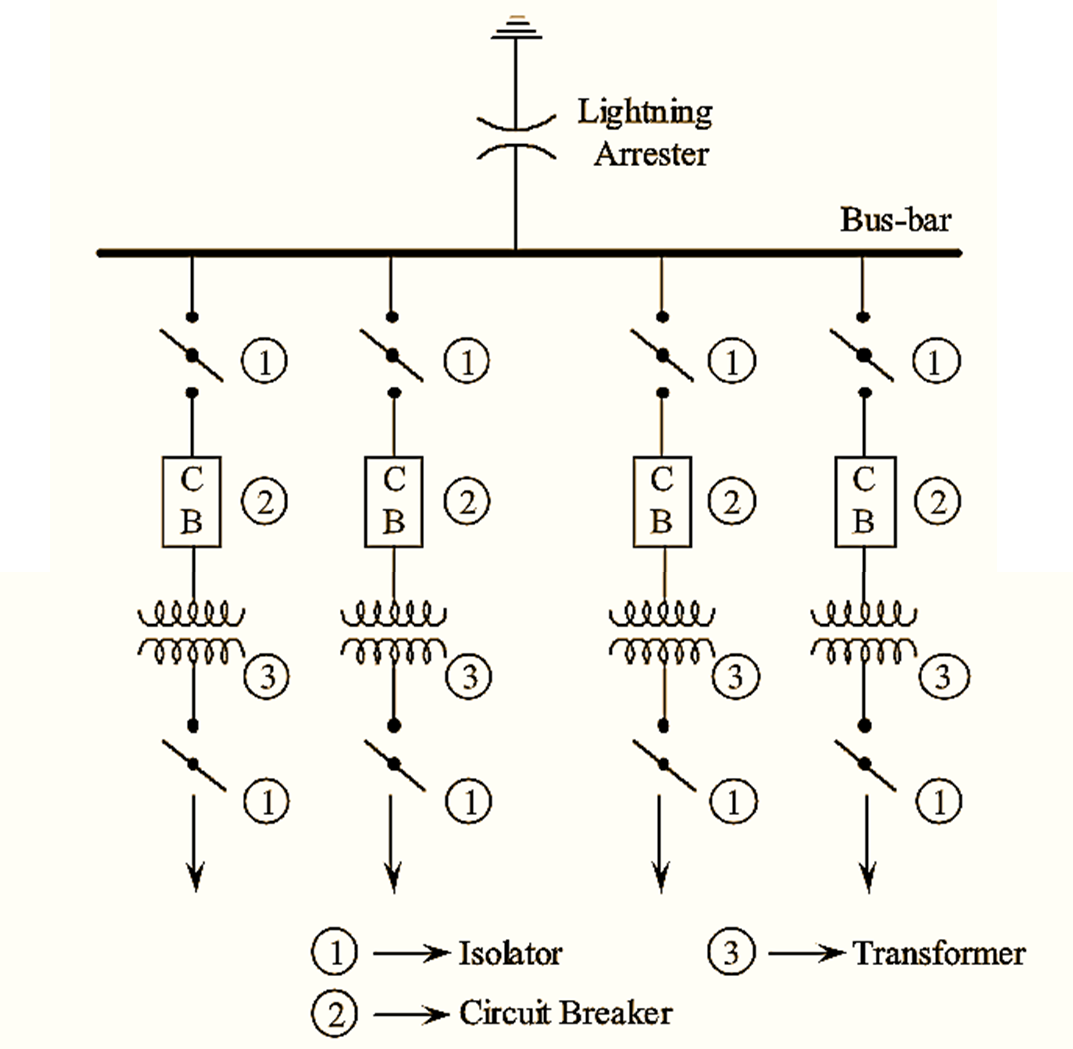
Single bus-bar system is the simplest and cheapest arrangement of bus-bars. It consists of a single bus-bar to which all the electrical equipments viz., generators, transformers, isolators, etc., are connected. A circuit breaker is provided for every individual equipment for protection against fault currents. Similarly, isolators helps in the isolation of generators, transformers etc., during fault clearance and maintenance.
Single bus-bar system is used for voltages below 33 kV. Usually, it is employed for 11 kV indoor substations. Single line diagram of a single bus-bar system is shown in the following figure. Further, it is to be noted that all the incoming and outgoing lines are connected to the single bus-bar only. The incoming lines at a voltage of 11 kv are connected to the bus-bar through isolators and circuit breakers. In the outgoing line, the voltage is stepped down to 400 V using 11 kV/400 V transformer, thereby making the voltage at outgoing lines to 400 V
Advantages of Single Bus-bar System
- Due to the simplicity and low initial cost, single bus-bar systems are used.
- It is easy to operate since, the connections of single bus-bar system are simple.
- Single bus-bar system can be conveniently used where there is no future expansion of the substation is expected.
Disadvantages of Single Bus-bar System
- In case of fault on the bus-bars, the supply to the whole system, including healthy feeders gets interrupted.
- It is not possible to carry out repairs without interrupting the supply.
Single Bus-bar with Sectionalizer

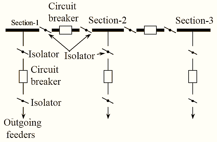
Sectionalized single busbar means single busbar with 2 to 3 sections. Sections of busbar are separated by isolator with circuit breaker combination as shown in figure. Sectionalization of busbar with only isolator is not preferable. We know that isolator is also called as no-load switch i.e., which works on no-load only. Hence, a circuit breaker is necessary to remove the load on bus-bar. It is clear that sectionalization of busbar prefers isolator with circuit breaker.
Sectionalized single bus-bar has following advantages (over single bus-bar arrangement),
Advantages of Single bus-bar with sectionalizer
- Flexible operation can be achieved using single bus-bar scheme with sectionalization.
- More reliable than simple bus-bar scheme.
- The faulted section can be isolated without affecting the other section’s supply.
- The maintenance or repair of one section is possible as it is shut downed, without affecting the other section supply.
Disadvantages of Single bus-bar with sectionalizer
- If the circuit breakers are not used as the sectionalizing switch, then the coupling of the bus-bar may occur during the load transfer and the use of circuit breakers make the system expensive.
- In order to maintain the continuity of supply to the system, during the maintenance of the circuit breaker, the circuit breaker must be provided with isolators on both sides, which further increases the cost of the system.
- Single bus-bar system with sectionalization is uneconomical for small substations.
Main and transfer bus-bar system

Bus-bars are the copper rods, that are used to collect electrical energy at one place. The generators and feeders that are operating at same voltage (or) constant voltage are connected directly to these busbars. In order to avoid the interruption of power flow the study of bus-bar arrangement is very important.
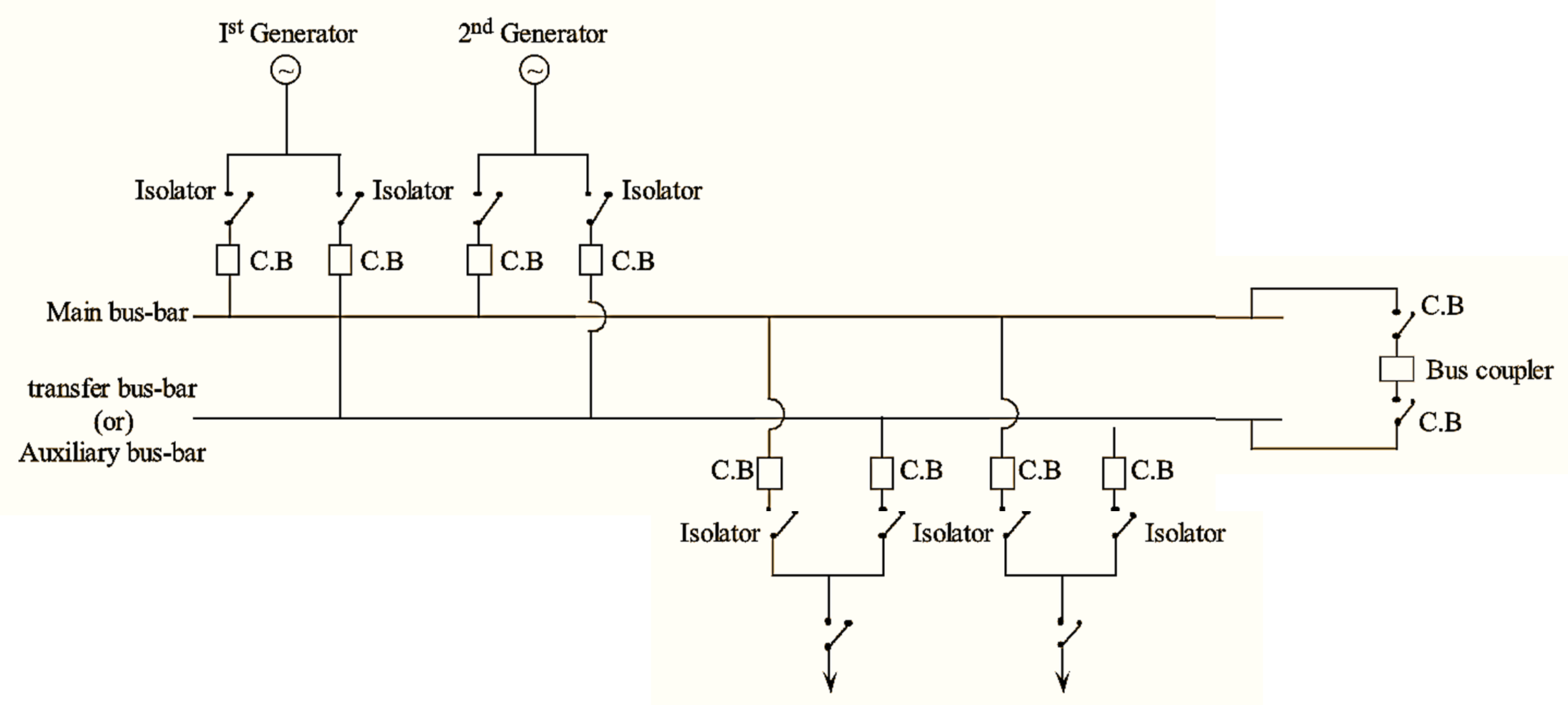
The main and transfer busbar arrangement uses two buses, one as main bus and other as transfer (or) auxiliary (or) spare bus. The generators and feeders are connected to both main bus and as well as transfer (or) auxiliary bus.
Under normal conditions the generator and feeder, are connected to main bus. Suppose, assume that the fault has occurred in any breaker or main bus then the power flow gets interrupted. In order to avoid this, the entire equipment that are connected to main bus is shifted (or) transferred to a transfer bus (or) auxiliary bus without any interruption of power flow by using a bus- coupler, which uses double isolating switches. Thus the generator and feeders are transferred from main bus to auxiliary bus without any interruption of power.
Advantages of Main and Transfer Bus-bar System
- There is no interruption of power supply i.e., the power supply is continuous even under fault condition.
- The maintenance and repair of bus or circuit breaker is easy.
- During fault conditions the circuit is transferred easily to an auxiliary bus.
Disadvantages of Main and Transfer Bus-bar System
- The main and transfer bus-bar arrangement is very expensive than other bus-bar arrangements.
- The service may be interrupted during switch over from one bus to another bus.