When a DC generator is loaded, the current flows through the armature winding, commutator and brushes to the external circuit. During this process, whenever a brush spans the two commutator segments, the winding element connected to those commutator segments is short-circuited. The changes in current direction, which take place in the winding part, just before, during and after the short circuit is called commutation.
Commutation Process
If the change in the current direction is gradual, then a smooth commutation takes place. On the other hand a sudden change in current in the winding element is called rough commutation which results in heavy sparking at the sides of brushes. If rough commutation is allowed to continue, the brushes and commutator get spoiled ultimately due to the excess heat produced by the sparks.
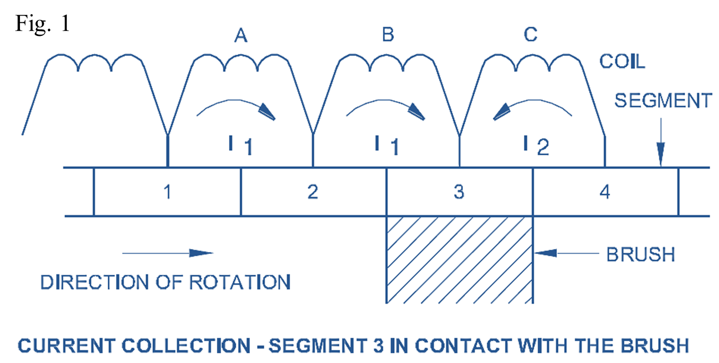
These changes in current are explained through the following figures. Fig 1 shows the current in the coil B flows in a clockwise direction, and the brush collects I1 amps from the left side winding and I2 amps from the right side winding.
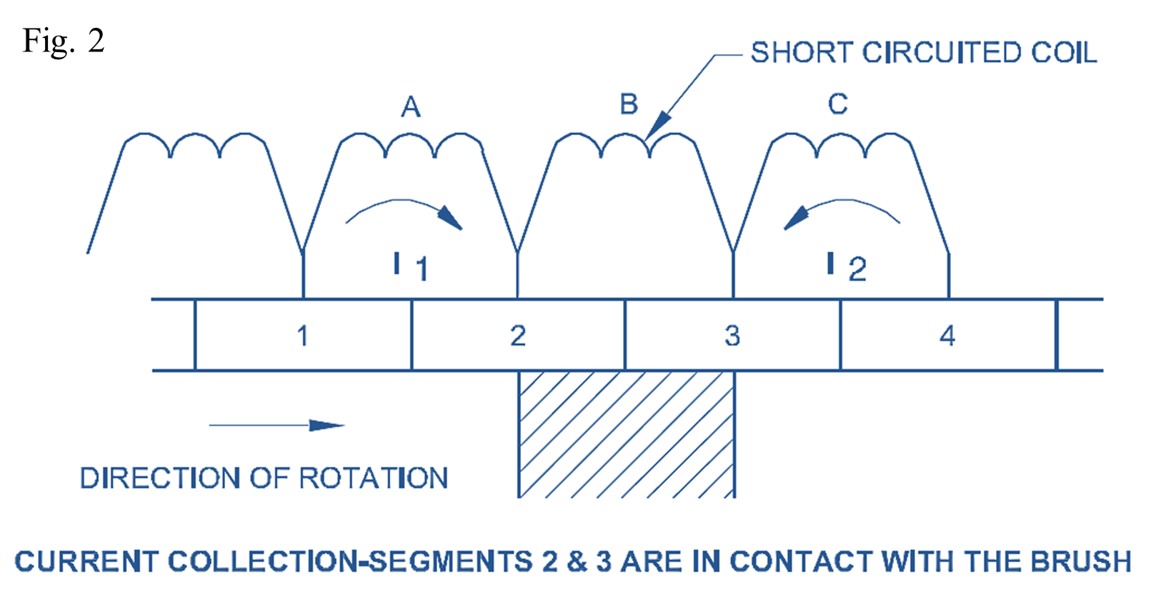
Fig 2 shows that the brush short-circuits segments 2 and 3, and hence, coil B is short-circuited. Current I1 in the left side winding passes to the brush through coil A, and the right side winding current passes through coil C. No current is in coil B as it is short-circuited.
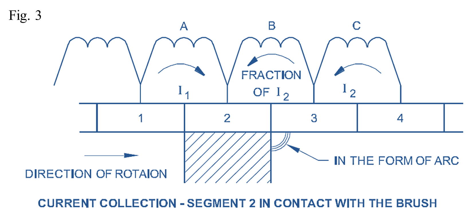
Fig 3 shows that the brush contacts segment 2 only, and the current in the left side winding passes to the brush through coil A. On the other hand the current in the right-hand side (I2) should now pass through coil B via segment 2 to the brush.
At this instant, the current in coil B, has to change its direction from clockwise to anticlockwise, but even though it changes it would not attain the full value of current after the short circuit. Therefore, a major portion of current I2 from the right side passes to the brush through an arc from segment 3. This is due to the fact that the sudden change of current direction in coil B induces a statically induced (reactance) emf equal to
\[\frac{\phi }{t}\text{ or }\frac{I}{t}\]
where Φ is the flux created by the current I in amps, and ‘t’ represents the time of short circuit in seconds.
Further, the induced emf can also be calculated by knowing the reactance of the coil under commutation which depends upon the self-inductance of the coil, and the mutual inductance of the neighbouring coils.
For example, a 2-pole, 2-brush DC generator delivers 100 amps to a load when running at 1440 r.p.m., and has 24 segments in its commutator. Then to find the statically induced emf in the winding element soon after the short-circuit, we have the current from the left side of the brush is 50 amps and the current from the right side of the brush is 50 amps.
Hence the change of current is from 50 amps in the clockwise direction to zero, then to 50 amps in the anticlockwise direction amounting to 100 amps.
Time is taken for one revolution
\[=\frac{60}{1440}=0.04166\text{ seconds}\].
Time taken for short circuit
\[=\frac{0.04166\text{ seconds}}{24\text{ segments}}=0.001736\text{ seconds}\]
which is equal to time reqd. to pass one segment
Hence the statically induced emf
\[=\frac{I}{t}=\frac{100}{0.001730}\text{ }=57,803\text{ V}\]
This induced emf will obey Lenz’s law, and oppose the change in the current. Hence the current from the right-hand side as shown in Fig 3 would not be able to pass through coil B, and hence it jumps to the brush in the form of an arc. This is called rough commutation.
Remedies for Rough commutation by providing Interpoles
To avoid sparks in the brush position, the following methods are used which effectively change the rough commutation to smooth commutation.
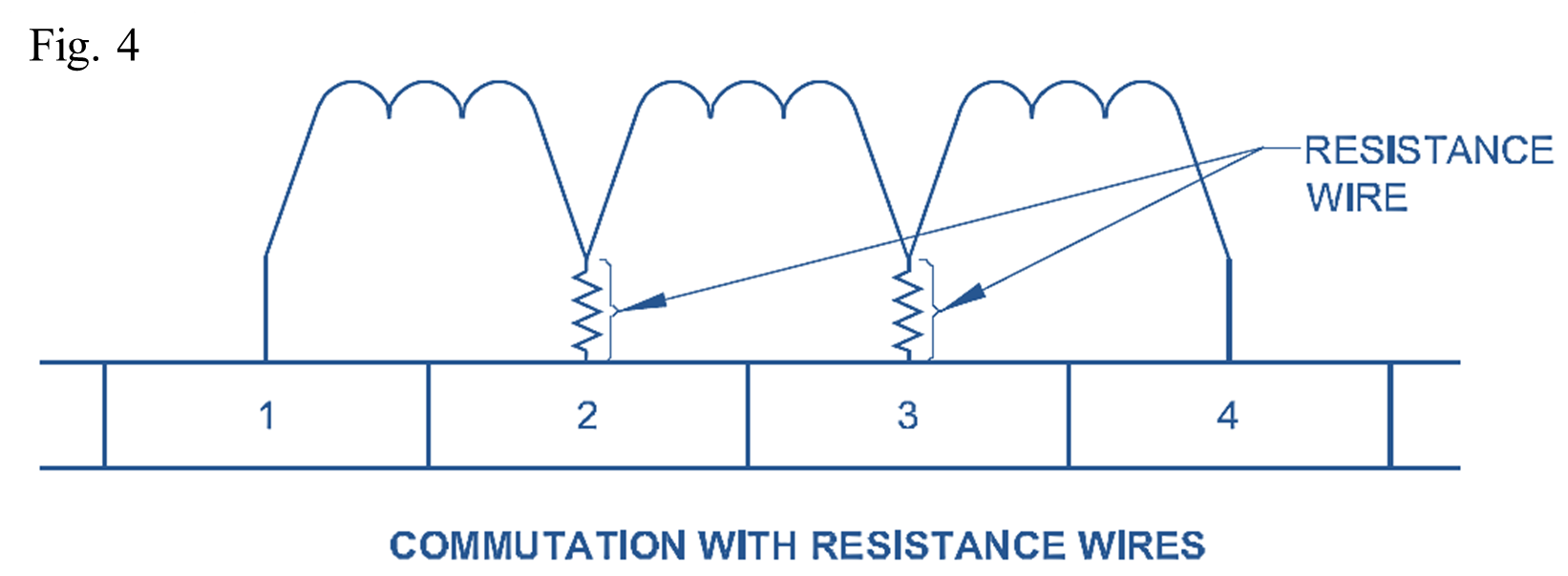
- Resistance wires are introduced between the end connection of the coil to the commutator, as shown in Fig 4. This increased resistance helps the current to change its direction smoothly, increasing the timing and reducing the statically induced emf.
- High-resistance brushes are used. Hence the contact resistance variation allows the current to change its direction smoothly, thereby reducing the statically induced emf.
- Small field poles called interpoles are provided in between the main poles as shown in Fig 5. These inter-poles have their polarity the same as the next pole ahead in the direction of rotation of the generators. Further, their winding is connected in series with the armature so that they carry the same current as that of the armature.
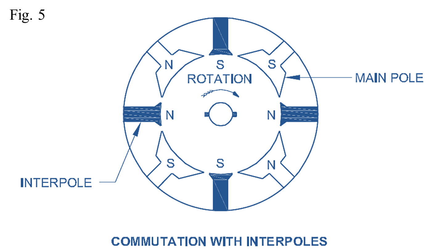
These inter-poles produce an emf opposite in direction to the statically induced emf, and have a magnitude depending upon the current. Thereby, the effect of statically induced emf is nullified.
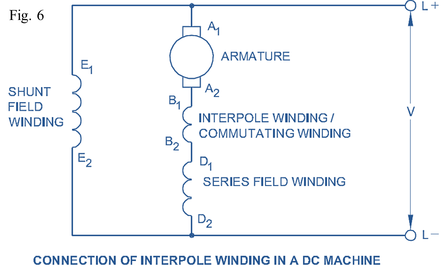
These inter-poles are wound with less number of turns having thick gauge wire. Fig 6 shows the connection of inter-pole winding in a DC compound machine.