A center-tapped full-wave rectifier is an electrical circuit used to convert alternating current (AC) into direct current (DC). It is commonly used in power supplies to ensure efficient DC voltage conversion.
What is Center Tapped Full Wave Rectifier?
A center-tapped full-wave rectifier is a type of rectifier circuit that uses a center-tapped transformer and two diodes to convert both halves of the AC input waveform into a pulsating DC output. The center tap of the transformer acts as a reference point, allowing both positive and negative halves of the AC waveform to be utilized.
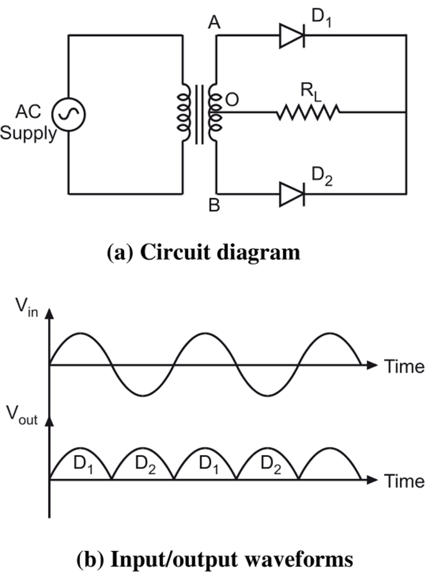
Figure 1.
Circuit Diagram of Center Tapped Full Wave Rectifier
The circuit (see Figure 1(a)) consists of:
- AC Supply: Provides alternating voltage.
- Center-Tapped Transformer: Steps down or steps up the AC voltage and provides a center tap as a neutral reference.
- Diodes (D1 and D2): Rectify the AC voltage by allowing only one direction of current flow.
- Load Resistor (RL): Converts rectified voltage into useful DC output.
Working Principle of Center Tapped Full Wave Rectifier
The working of a center-tapped full-wave rectifier is based on the principle of rectification, where diodes allow current flow in only one direction. The center-tapped transformer provides two equal and opposite AC voltages with respect to the center tap, enabling the use of two diodes for rectification.
Operation of Center Tapped Full Wave Rectifier
Positive Half-Cycle
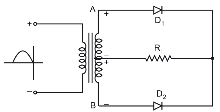
During the positive half-cycle of the AC input, terminal A is positive, and terminal B is negative. Diode D1 becomes forward-biased, allowing current to pass through the load RL. Diode D2 is reverse-biased and blocks current flow.
Negative Half-Cycle
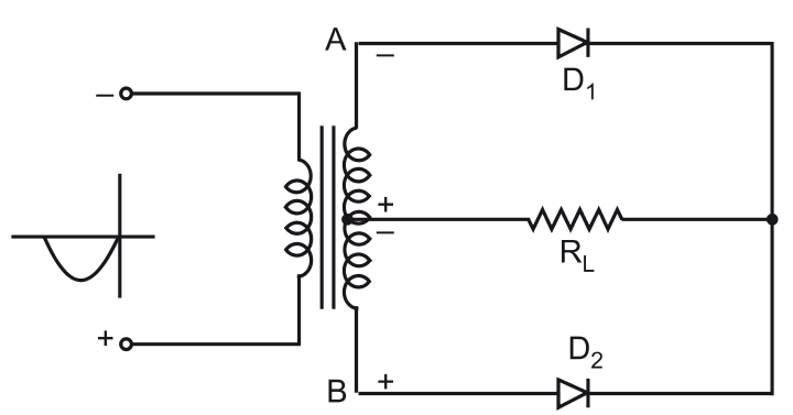
During the negative half-cycle of the AC input, terminal B becomes positive, and terminal A becomes negative. Diode D2 is forward-biased, allowing current to pass through the load RL in the same direction. Diode D1 is reverse-biased and blocks current flow.
Thus, both half-cycles contribute to current flow in the same direction across the load resistor, resulting in a full-wave rectified output.
Waveforms of Center Tapped Full Wave Rectifier
The input and output waveforms (see Figure 1(b)) are as follows:
Input Voltage (Vin): A sinusoidal waveform with alternating positive and negative cycles.
Output Voltage (Vout): A pulsating DC waveform with only positive cycles due to rectification by D1 and D2.
Advantages of Center Tapped Full Wave Rectifier
- Higher efficiency compared to half-wave rectifiers.
- Utilizes both halves of the AC waveform, reducing ripple.
- Provides higher DC output voltage.
Disadvantages of Center Tapped Full Wave Rectifier
- Requires a center-tapped transformer, increasing cost and size.
- Diodes must withstand full secondary voltage, requiring higher ratings.
Applications of Center Tapped Full Wave Rectifier
- DC Power Supplies: Used in household electronic devices, chargers, and adapters.
- Battery Charging Circuits: Provides regulated DC voltage for charging batteries.
- Audio and Radio Circuits: Used in audio amplifiers and radio receivers.
- Industrial Electronics: Used in motor controllers and DC-powered control systems.
Conclusion
The center-tapped full-wave rectifier is an efficient rectification technique, widely used in power electronics. It provides a smooth DC output with reduced ripple compared to half-wave rectifiers. Despite the requirement of a center-tapped transformer, its advantages make it a preferred choice for many applications.