An AC voltmeter is an electrical measuring instrument used to measure the magnitude of alternating voltage between two points in an AC circuit. Unlike a DC voltmeter, it is designed to measure voltages that continuously change in magnitude and polarity with time. AC voltmeters are widely used in electrical power systems, laboratories, and electronic
circuits for voltage measurement and analysis.
Working Principle of AC Voltmeter
Most AC voltmeters operate on the principle that an alternating voltage must first be converted into a proportional DC quantity, because indicating instruments generally respond only to DC. The AC signal is processed through rectifiers, amplifiers, or thermal converters, and the resulting DC output is used to drive the meter movement.
Block Diagram of Electronic AC Voltmeter
Block Diagram Explanation
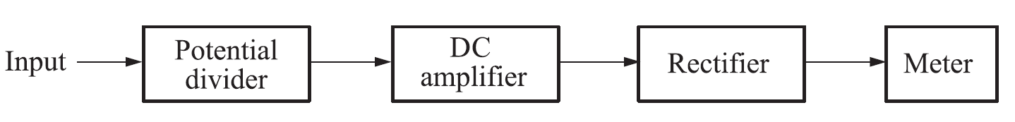
The block diagram of an electronic AC voltmeter consists of the following sections:
1. Potential Divider
The input AC voltage is first applied to a potential divider circuit. This circuit reduces the input voltage to a suitable level and allows the instrument to measure different voltage ranges safely.
2. DC Amplifier
The reduced voltage is then applied to a DC amplifier. The amplifier increases the magnitude of the signal without changing its waveform, which improves the sensitivity and accuracy of the voltmeter.
3. Rectifier
The amplified AC signal is passed through a rectifier circuit. The rectifier converts the alternating voltage into a unidirectional DC voltage that can be measured by the meter.
4. Meter
The rectified DC output is finally applied to the indicating meter. The meter scale is calibrated in terms of AC voltage, so the reading directly represents the applied AC voltage.
Types of AC Voltmeters
AC voltmeters are classified into the following three categories:
1. Average Reading AC Voltmeter
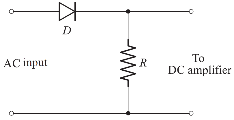
The simplified circuit of an average reading voltmeter measures the average value of an alternating voltage by rectifying only one half of the input waveform. The operation of
the instrument depends on the orientation of the diode used in the circuit.
When the diode is connected to conduct during the positive half-cycle of the AC input, it becomes forward biased and allows current to flow. This results in half-wave rectification of the input signal. The average value of the positive half-cycle appears across the resistor connected in the circuit.
This voltage developed across the resistor is applied to the DC amplifier and the indicating meter, which responds to the average value of the rectified signal. During the negative half-cycle, the diode remains reverse biased and no current flows.
If the diode connection is reversed, the circuit operates in the same manner but conducts during the negative half-cycle instead of the positive one. In this case, the meter indicates the average value of the negative half of the AC input voltage.
Mathematical Expression
Let the input AC voltage be:
\[
v(t) = V_m \sin(\omega t)
\]
The average value of a half-wave rectified sine wave over one complete cycle is:
\[
V_{avg} = \frac{1}{2\pi} \int_{0}^{\pi} V_m \sin(\theta)\, d\theta
\]
Solving the integral gives:
\[
V_{avg} = \frac{V_m}{\pi}
\]
For a sinusoidal waveform, the RMS value of the voltage is:
\[
V_{rms} = \frac{V_m}{\sqrt{2}}
\]
Hence, the RMS value in terms of average value is:
\[
V_{rms} = 1.11 \, V_{avg}
\]
In practical average reading voltmeters, the scale is calibrated using this relation so that the meter directly indicates RMS voltage for a sinusoidal AC input.
2. Peak Reading Voltmeter
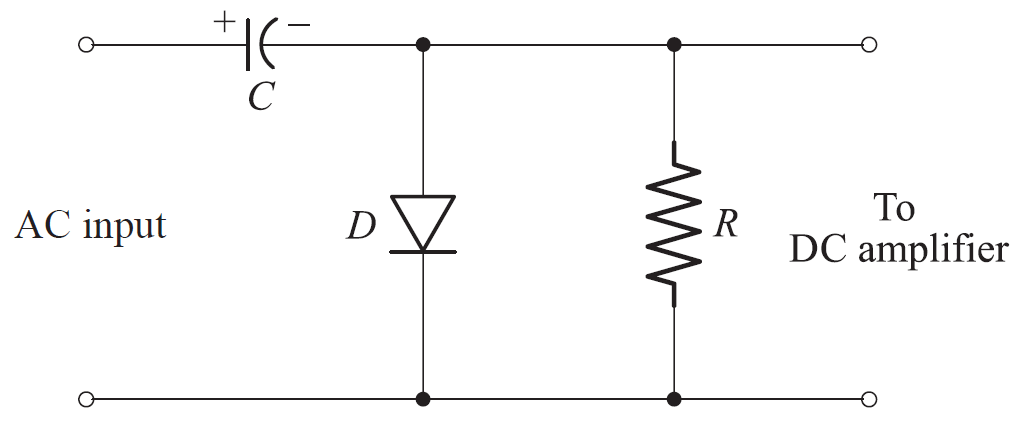
In this circuit, the diode D is connected in such a way that it becomes forward biased during the positive half-cycle of the applied AC voltage. As a result, the capacitor charges quickly up to the positive peak value of the input signal. Due to the unidirectional conduction property of the diode, the charge stored on the capacitor does not leak away rapidly. Consequently, the voltage applied to the meter remains close to the peak value of the input voltage.
The resistance value of R is selected such that it is greater than the forward resistance of the diode but much smaller than the reverse resistance. When the diode is forward biased, the capacitor charges through the diode. When the diode becomes reverse biased during the negative half-cycle, the capacitor discharges slowly through the resistor R. This slow discharge ensures that the output voltage closely follows the peak value of the input.
If the diode connection is reversed, the circuit operates in a similar manner, but the meter indicates the negative peak value of the applied AC voltage instead of the positive peak.
Peak reading voltmeters, also known as peak detectors, are commonly used in coaxial configurations for very high-frequency measurements. By placing the diode and capacitor inside the probe, signals with frequencies up to approximately 40 GHz can be measured without directly applying them to the amplifier or meter.
In average reading voltmeter circuits, the AC input is first full-wave rectified. The low-pass filtering action of the meter movement is then used to obtain the average value of the rectified voltage.
In contrast, RMS reading meter circuits approximate the required square-law relationship using multiple straight-line segments, similar to the operation of a diode function generator. Although the voltage applied to the meter is an average value, the meter scale is calibrated to indicate the RMS value.
Mathematical Relations
For a sinusoidal input voltage,
\[
v(t) = V_m \sin(\omega t)
\]
the capacitor charges approximately to the peak value,
\[
V_{peak} \approx V_m
\]
The corresponding RMS value for a sinusoidal waveform is,
\[
V_{rms} = \frac{V_m}{\sqrt{2}}
\]
Hence, although the circuit detects the peak value, the instrument scale is calibrated to display the RMS value of the input voltage.
3. True RMS Responding AC Voltmeter
A true RMS voltmeter measures the actual RMS value of the applied AC voltage regardless of its waveform. These voltmeters provide the highest accuracy and are commonly used in modern electronic and industrial applications.
Advantages of AC Voltmeter
- Accurate measurement of alternating voltages
- High input impedance reduces loading effect
- Suitable for a wide range of frequencies
- Easy to use and reliable
Disadvantages of AC Voltmeter
- Average responding meters are inaccurate for non-sinusoidal waveforms
- True RMS voltmeters are costly
- Accuracy decreases at very high frequencies
- Electronic components may drift with temperature
Applications of AC Voltmeter
- Measurement of mains and supply voltages
- Testing and troubleshooting electrical equipment
- Laboratory and educational experiments
- Power system monitoring
- Electronic circuit testing
DC voltmeter like PMMC meter works on DC supply but this meter can work on AC supply as if it is a AC voltmeter.
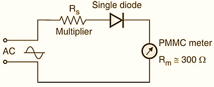
Figure 1.
What is required is an additional device to be connected between AC supply and PMMC meter is a Rectifier unit. If single diode is used as a rectifying unit for AC to DC conversion, then meter connected to output of rectifier serves as AC voltmeter with half wave type.
If for rectification 4-diode unit in the bridge form is used it will be a full wave type. Such rectifier instruments are suitable for measurement on communication circuits and also for low voltage light current work. Multiplier resistance (Rs) is used in series with the instrument for controlling the current to the safe value. Both such half wave and full wave rectifier units with the meter are explained with circuit arrangement below.
Half Wave Rectifier Circuit for AC Voltmeter
As shown in the Fig. 1 a single diode is connected to AC supply and PMMC instrument. Diode acting as rectifier converts AC into DC fed to the PMMC meter. Rs is the multiplier resistance connected in series. Current through the meter (Im) is given by the relation.
\[{{I}_{m}}=\frac{V}{{{R}_{m}}+{{R}_{s}}}\]
where Rm is the meter resistance, this produces full scale deflection.
Because of the inertia of moving parts PMMC indicates a deflection corresponding to the average value of current which is dependent upon the average value of the applied voltage. Sensitivity of this instrument is ac 0.45 times its sensitivity with dc.
Full Wave Rectifier Circuit for AC Voltmeter
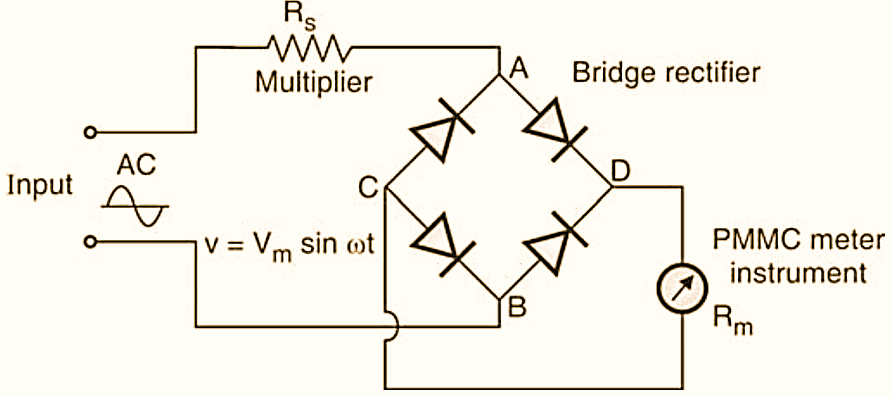
Figure 2.
As said earlier, in this type for rectification (ac → to dc) a full wave bridge circuit is used using 4 diodes. See the connection of this bridge with AC and PMMC instrument in the Fig. 2. Across point A and B, ac voltage is connected to the bridge circuit, where as d.c. is available as output voltage from the bridge to which PMMC meter is connected. The current through the meter is given as,
\[{{I}_{m}}=\frac{V}{{{R}_{m}}+{{R}_{s}}}\]
This current causes full scale deflection of the meter. The sensitivity of full wave rectifier type of instrument with a sinusoidal ac as an input is 90% of that with dc voltage of the same magnitude. The sensitivity of the full wave rectifier type of instrument is two times that of the half wave rectifier type.
Note that the scale markings of the meters are made with using a multiplier factor of 1.11 in case of instrument using full wave rectifier and that factor is 2.22 in case of half wave type instrument.
Conclusion
An AC voltmeter is an essential instrument for measuring alternating voltages in electrical and electronic systems. Depending on the accuracy requirement and waveform type, average responding, peak responding, or true RMS voltmeters can be selected for reliable voltage measurement.