Linear Variable Differential Transformer (LVDT) is one of the most popular electromechanical transducers used for precise measurement of linear displacement. It converts small mechanical movement of a soft iron core into a proportional electrical voltage. Because of its high accuracy, reliability and frictionless operation, the LVDT is widely used in industrial control, automation, aerospace, power plants and research laboratories.
An LVDT is an AC transducer that converts linear displacement of a movable magnetic core into a differential AC voltage across two secondary windings.

Construction of LVDT
The basic construction of a Linear Variable Differential Transformer is similar to a special type of transformer. It consists of one primary winding and two secondary windings wound on a hollow cylindrical former. A soft iron movable core slides freely inside this former. The important constructional parts are:
1. Soft Iron Core
The core is made of high-permeability soft iron or nickel–iron alloy. It is usually attached to a non-magnetic rod (e.g. stainless steel or plastic) which is mechanically linked to the object whose displacement is to be measured. The core moves linearly inside the hollow former without any physical contact with the windings, hence the operation is frictionless.
2. Primary Winding
A single primary winding is placed exactly at the centre of the former. It is excited by a sinusoidal AC supply (typically 1–10 kHz, a few volts). The alternating current produces an alternating magnetic flux which links both secondary windings through the movable core.
3. Secondary Windings S1 and S2
Two identical secondary windings, named S1 and S2, are wound symmetrically on both sides of the primary. They have equal number of turns and are connected in series opposition (differential connection). This means that the induced voltages in the secondaries subtract from each other. The output of the LVDT is taken as the differential voltage:
eout = e1 − e2
where e1 and e2 are the voltages induced in S1 and S2 respectively.
4. Former and Housing
The windings are wound on a hollow, non-magnetic, insulating former (often glass-fibre or plastic). The entire assembly is enclosed in a protective case or housing, which may be made of non-magnetic stainless steel or aluminium. Some designs include magnetic shielding to reduce the effect of external fields and improve accuracy.
5. Electrical Terminals
Separate terminals are provided for the primary and secondary windings. In many industrial LVDTs, integral connectors or cables are provided for easy wiring to signal-conditioning electronics.
Working Principle of LVDT
The LVDT works on the principle of mutual induction in a transformer. The primary winding is excited by AC supply and an alternating magnetic flux is produced inside the core. This flux links the two secondary windings and induces voltages in them which depend on the position of the movable core.
1. Core at Null Position
When the core is at the exact centre of the primary winding, it links equal flux with both secondary windings. Therefore, the voltages induced in S1 and S2 have equal magnitude but are 180° out of phase due to series-opposed connection. The resulting differential output voltage is:
eout = e1 − e2 ≈ 0
This position is called the null point. In theory the output is zero, but in practice a very small residual voltage appears because of imperfect symmetry, leakage flux and other non-idealities.
2. Core Displaced Towards S1
When the core moves towards secondary winding S1, more magnetic flux links S1 and less links S2. Therefore:
- |e1| > |e2|
- Differential output: eout = e1 − e2 is in phase with the primary voltage.
The magnitude of eout increases approximately linearly with the distance of the core from the null position. The phase relationship with the primary signal indicates the direction of displacement.
3. Core Displaced Towards S2
When the core moves towards secondary winding S2, the situation reverses:
- |e2| > |e1|
- Differential output: eout = e1 − e2 becomes opposite in phase to the primary voltage.
Thus, not only the magnitude but also the phase of the output voltage provides information about the direction and amount of displacement.
4. Output Characteristics
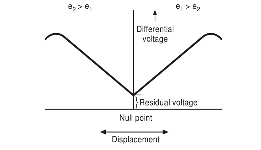
If we plot the differential secondary voltage eout against core displacement, we obtain a straight line on either side of the null position within a certain range. Beyond this linear range, the characteristic begins to curve and non-linearity increases. The useful stroke of an LVDT is chosen within this linear region where the relationship between displacement and output voltage is nearly proportional.
eout ∝ x,
where x is the linear displacement of the core from null position.
Types of LVDT
LVDTs are classified in different ways depending on construction and associated electronics. Important types are summarised in the following table.
| Type of LVDT | Construction / Feature | Core Movement Mechanism | Advantages | Typical Applications |
|---|---|---|---|---|
| AC–AC LVDT (Conventional) | Primary excited by AC supply; secondaries give AC differential output that must be demodulated. | Free-moving soft iron core connected to external mechanism. | Simple, robust, high temperature capability, very long life. | Industrial displacement sensors, servo mechanisms, power plant monitoring. |
| DC–DC LVDT (with built-in electronics) | Contains internal oscillator, rectifier and amplifier; gives DC output proportional to displacement. | Same mechanical core, but electronics integrated into housing. | Direct DC output, easy interface with PLCs and controllers, less external wiring. | Automation systems, PLC/SCADA based control, test rigs. |
| Captive (Guided) Core LVDT | Core is mechanically guided inside bore using low-friction bearings. | Limited stroke; core attached via guided rod to moving part. | Excellent repeatability, suitable for high-vibration environments. | Hydraulic and pneumatic actuators, servo valves, machine tools. |
| Unguided Core LVDT | Core is completely loose and not mechanically attached to housing. | Core moved only by external mechanical linkage or gravity. | No friction between core and bore; very high reliability and long life. | Precision instruments, low-force measurements, research setups. |
| Spring-Extended LVDT | Includes an internal spring that pushes the core to a normally extended position. | Core follows surface by spring force; self-returning probe. | Suitable for measuring position against a surface without external mechanism. | Dial-type displacement gauges, surface profiling, dimensional inspection. |
| Submersible / High-Temperature LVDT | Special sealing and materials for harsh environments (oil, water, high temperature). | Core and housing designed to withstand pressure and temperature. | Reliable in extreme industrial and aerospace conditions. | Nuclear reactors, turbine position monitoring, underwater equipment. |
Advantages of LVDT
LVDTs are very popular because they offer several important advantages over other displacement sensors such as potentiometers or strain-gauge based devices.
- Frictionless operation: There is no mechanical contact between the core and the coil structure, so there is practically no wear and extremely long service life.
- Infinite resolution: Since the output is analog and not quantised, theoretically there is no limit to the resolution, which is only restricted by the associated electronics.
- High accuracy and linearity: Within its specified range, an LVDT can provide linearity as good as ±0.25% or better of full-scale output.
- Large measurement range: Stroke lengths vary from a few millimetres to several hundred millimetres without major loss of accuracy.
- High sensitivity: Small displacements produce measurable output voltages, making LVDTs suitable for precision measurements.
- Rugged and reliable: The simple and solid construction allows operation in vibration, shock and harsh industrial environments.
- Electrical isolation: Primary and secondary windings are electrically isolated, which improves safety and reduces interference.
- Bipolar displacement measurement: Movement in both positive and negative directions from the null point can be measured with a single device.
Disadvantages of LVDT
Despite many advantages, LVDTs also have some limitations which must be considered while selecting a sensor for a particular application.
- Requires AC excitation and signal conditioning: Conventional LVDTs need an AC source and demodulator/phase-sensitive detector to convert the output into a usable DC signal.
- Sensitive to stray magnetic fields: External magnetic fields can influence the output unless proper shielding is provided.
- Limited frequency response with external electronics: When used with certain conditioning circuits, high-frequency dynamic measurements may be limited.
- Size and cost: For very small stroke lengths, other sensors like potentiometers can be smaller and cheaper.
- Temperature effects: Changes in temperature may affect coil resistance and output unless compensated.
Applications of LVDT
Because of their reliability and accuracy, LVDTs are used in a wide variety of measurement and control applications.
1. Industrial and Process Control
- Position feedback in servo mechanisms and closed-loop control systems.
- Measurement of valve position in power plants, refineries and process industries.
- Control of hydraulic and pneumatic cylinders and actuators.
- Monitoring expansion, thermal growth or structural movement in bridges and buildings.
2. Mechanical and Manufacturing Engineering
- Tool position feedback in CNC machines and automatic assembly lines.
- Measurement of thickness, flatness and surface profile of mechanical components.
- Dimensional inspection gauges, dial-type probes and micrometers.
3. Automotive and Aerospace
- Suspension travel and damper position in vehicles.
- Throttle, brake and steering position sensing.
- Flap position, landing-gear position and actuator feedback in aircraft.
4. Research, Testing and Laboratories
- Vibration and fatigue testing, measurement of dynamic displacement.
- Material testing machines for tensile and compression testing.
- Geophysical and seismological measurements where small displacements must be recorded.
5. Power and Energy Systems
- Turbine blade and servo-valve position measurement in power plants.
- Control rod position in nuclear reactors (using radiation-resistant LVDTs).
- Monitoring of dam gates and spillway gates in hydroelectric stations.
Summary
The Linear Variable Differential Transformer is a versatile and accurate transducer for linear displacement measurement. It consists of a primary and two secondary windings with a movable soft iron core. AC excitation of the primary produces differential voltages in the secondary windings whose magnitude and phase depend on the position of the core. Within its linear range, the output voltage is directly proportional to displacement, making the LVDT easy to calibrate and use.
With its frictionless construction, high resolution and long life, the LVDT remains a preferred choice for precision displacement measurement in industrial automation, aerospace, automotive, energy systems and scientific research. Proper selection of type, stroke length and signal-conditioning electronics allows the same basic principle to be successfully applied in a wide range of modern engineering applications.