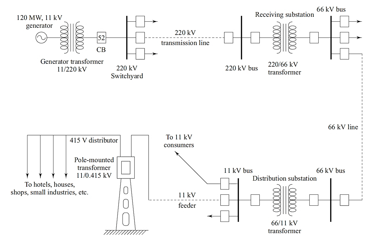
A single-line diagram (SLD) is a simplified representation of an electrical power system that uses a single line to show all three phases of a three-phase system. It highlights the flow of power from generation to distribution, incorporating essential system components.
Components of Single Line Diagram of Power System

A Single Line Diagram (SLD) showcases all the major components of a power system in a simplified manner. Each component has a specific role in the generation, transmission, and distribution of electrical power. Here’s a detailed breakdown of the components:
Generator
- Function: Converts mechanical energy (from steam, gas, water, or wind) into electrical energy.
- Representation: Shown as a circular symbol with a label for capacity, e.g., “120 MW.”
- Details:
- Typically operates at a lower voltage, such as 11 kV or 13.8 kV.
- Connected to a step-up transformer to increase voltage for transmission.
Transformer
- Function: Changes voltage levels for efficient power transfer. Ensures voltage is stepped up for transmission (e.g., 11 kV to 220 kV) and stepped down for distribution (e.g., 11 kV to 415 V).
- Representation: Represented with two parallel coils, indicating primary and secondary windings.
- Types:
- Generator Transformer: Steps up voltage for long-distance transmission.
- Distribution Transformer: Steps down voltage for local use.
- Example in SLD: 11/220 kV generator transformer at the power plant and 220/66 kV transformer at the substation.
Circuit Breaker (CB)
- Function: Protects the system by interrupting the circuit during faults. Ensures safe disconnection of faulty sections.
- Representation: A rectangular box or labeled “52” (IEEE device number for a circuit breaker).
- Types:
- Air Circuit Breaker (ACB): For low voltage systems.
- SF₆ Circuit Breaker: For high voltage systems.
Busbar
- Function: Serves as a junction point to distribute power between incoming and outgoing circuits.
- Representation: Shown as a straight horizontal or vertical line in the SLD.
- Details: Designed to handle large currents. Located in substations to connect multiple circuits efficiently.
Transmission Lines
- Function: Transfers high-voltage power over long distances from generating stations to substations.
- Representation: Shown as dashed or solid lines between substations.
- Details: Operates at high voltages (e.g., 220 kV, 400 kV) to minimize power loss due to resistance. Insulated and supported by towers to maintain safety and reliability.
Load
- Function: Represents the end-users of electricity, including industries, homes, and commercial buildings.
- Representation: Shown as arrows or blocks connected to the distribution network.
- Details: May include resistive, inductive, or capacitive loads depending on application. Voltage levels for different loads:
- 415 V: Residential and small industries.
- 11 kV: Large industries.
Substation
- Function: Acts as a nodal point for voltage transformation, switching, and protection.
- Components within Substations:
- Transformer: Steps voltage up or down.
- Busbars: Distributes power within the substation.
- Circuit Breakers: Protect against faults.
- Types:
- Transmission Substation: Handles high voltages (e.g., 220 kV).
- Distribution Substation: Steps down voltage for local use (e.g., 66/11 kV).
Distribution System
- Function: Supplies electricity to end-users through feeders, distributors, and service mains.
- Key Components:
- Primary Distribution: Operates at 11 kV.
- Secondary Distribution: Operates at 415 V or lower.
- Pole-Mounted Transformers: Step down voltage for residential areas (e.g., 11 kV to 415 V).
- Representation: Arrows pointing towards consumers like hotels, houses, and small industries.
Protective Devices
- Function: Protects equipment and personnel from faults and abnormal conditions.
- Examples:
- Fuses: Provides overcurrent protection.
- Relays: Detect and isolate faults (e.g., overcurrent, earth fault).
- Lightning Arresters: Protects against voltage surges from lightning strikes.
Auxiliary Components
- Voltage Stabilizers: Maintain voltage levels to ensure system reliability.
- Control Panels: Monitor and control system operations.
- Meters: Measure voltage, current, power, and energy consumption.
Feeder
- Function: Distributes power from substations to the distribution transformers.
- Representation: Shown as lines connecting substations to transformers.
- Details: Operates at medium voltage levels like 11 kV.
Isolator
- Function: Disconnects portions of the power system for maintenance or safety.
- Representation: Shown as a simple switch symbol in SLDs.
- Details: Operates only under no-load conditions to isolate sections.
Explanation of the Diagram
The diagram is typically divided into three segments:
- Generation: Power generation occurs at low voltage (e.g., 11 kV) in power plants. A generator transformer steps up the voltage to 220 kV for efficient long-distance transmission.
- Transmission: High-voltage electricity (e.g., 220 kV or 66 kV) is transmitted through transmission lines to substations. Transmission reduces power loss and ensures reliable delivery.
- Distribution: At the receiving substation, voltage is stepped down to 66 kV or 11 kV using transformers. The distribution network supplies electricity to consumers, reducing voltage further to 415 V for small loads.
Need for Single Line Diagram of Power System
- Simplification: Represents complex three-phase systems with a single line for easy visualization.
- System Design: Helps engineers design and analyze power systems effectively.
- Fault Detection: Identifies weak points and potential overloads within the network.
- Operational Planning: Assists operators in planning maintenance and load distribution.
- Regulatory Compliance: Ensures the system meets safety and operational standards.