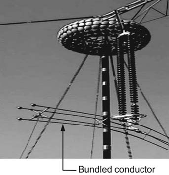
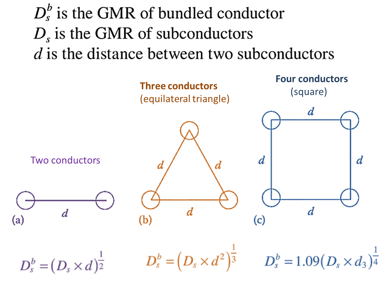
A bundled conductor is a configuration where multiple sub-conductors are grouped together and used as a single phase conductor in high-voltage (HV) or extra-high-voltage (EHV) transmission lines. These sub-conductors are separated by spacers to maintain their relative positions, typically arranged in geometric patterns like linear, triangular, or square configurations.

Difference between Bundled Conductors and Composite Conductors
| Aspect | Bundled Conductors | Composite Conductors |
|---|---|---|
| Definition | Multiple sub-conductors grouped and used as a single conductor in transmission lines. | A single conductor made of a composite core surrounded by aluminum strands. |
| Primary Purpose | Reduces corona loss, decreases reactance, and improves transmission efficiency. | Increases current-carrying capacity and mechanical strength while reducing sag. |
| Composition | Consists of 2–4 conductors arranged in specific configurations. | Made of a high-strength composite core and a conductive aluminum outer layer. |
| Material | Typically made of aluminum or aluminum alloy for sub-conductors. | Composite core (fiber-reinforced polymer) and aluminum for outer strands. |
| Weight | Heavier due to multiple sub-conductors and spacers. | Lighter than conventional conductors due to composite materials. |
| Electric Field Control | Reduces electric field intensity and voltage gradient. | Not directly designed for electric field control. |
| Sag Characteristics | Sag depends on the material of individual conductors and spacer placement. | Lower sag due to high-strength composite core. |
| Cost | Higher initial cost due to multiple conductors and spacers. | Higher material cost but may reduce long-term costs by avoiding tower upgrades. |
| Applications | Used in high-voltage (HV) and extra-high-voltage (EHV) systems. | Suitable for retrofitting existing lines to carry more power without upgrading towers. |
| Heat Dissipation | Better due to multiple conductor spacing allowing airflow. | Better thermal performance, withstanding higher operating temperatures. |
| Installation Complexity | Requires spacers and precise alignment of sub-conductors. | Easier to install as a single conductor without spacers. |
| Corona and Radio Interference | Minimizes corona discharge and radio noise effectively. | Less effective at reducing corona discharge compared to bundled conductors. |
Formula for the GMR (Geometric Mean Radius) of Bundled Conductors

Advantages of Bundled Conductors
- Reduced Corona Loss: Bundled conductors reduce the intensity of the electric field, minimizing corona discharge.
- Decreased Line Reactance: Helps reduce the inductance of the transmission line, improving power transfer capability.
- Reduced Voltage Gradient: Distributes the voltage gradient more evenly across conductors, reducing stress on insulators.
- Improved Transmission Efficiency: Lowers power losses due to reduced resistance and corona.
- Suppressed Radio Interference: Reduces high-frequency noise.
Disadvantages of Bundled Conductors
- Complex Construction: Bundling requires spacers and a proper framework, increasing design complexity.
- Higher Cost: The need for multiple conductors and spacers increases material and installation costs.
- Heavier Weight: Bundled conductors add to the weight of the transmission line, requiring stronger towers and support structures.
- Increased Maintenance: Extra components like spacers may require periodic inspections and maintenance.
Applications of Bundled Conductors
- High Voltage Transmission Lines: Commonly used in 220 kV and above to ensure stability and reduce line losses.
- Long-Distance Power Transfer: Efficient for transmitting large amounts of electricity over long distances.
- EHV and UHV Lines: Essential for extra-high-voltage (400 kV and above) and ultra-high-voltage (UHV) systems to manage electric field effects.
- Interstate or Intercountry Power Grids: Used in large-scale energy grids for effective power transfer.