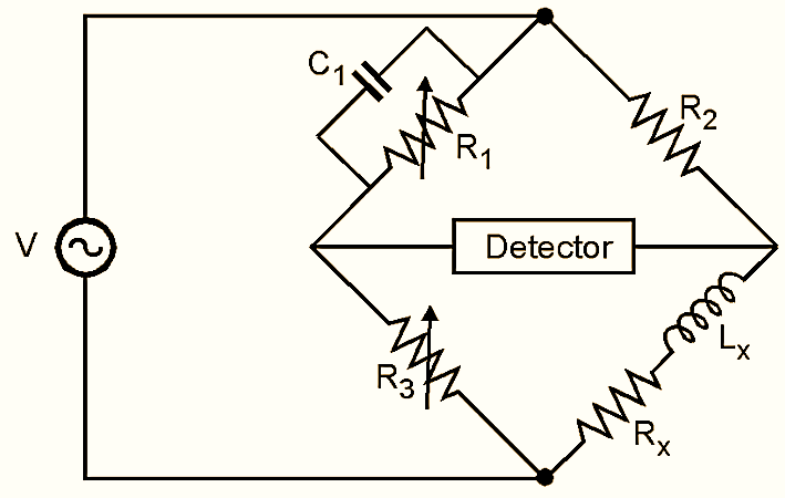
Maxwell’s Bridge method is used for measuring an unknown inductances of low Q values. It measures unknown inductance in terms of known capacitance. The circuit of Maxwell’s bridge is shown in Fig. 1. One arm of the bridge has resistor R1 in parallel with capacitor C1. The unknown inductor Lx with series resistor Rx is connected in one of the arms of the bridge.

Figure 1: Maxwell’s Bridge.
When bridge is balanced,
\[{{Z}_{1}{Z}_{x}}={{Z}_{2}{Z}_{3}}\]
\[{{Z}_{x}}=\frac{{{Z}_{2}}{{Z}_{3}}}{{{Z}_{1}}}={{Z}_{2}}{{Z}_{3}}{{Y}_{1}}\text{ }……\left( 1 \right)\]
\[{{Z}_{1}}={{R}_{1}}\parallel \frac{1}{j\omega {{C}_{1}}}\]
\[{{Y}_{1}}=\frac{1}{{{R}_{1}}}+j\omega {{C}_{1}}\]
\[{{Z}_{2}}={{R}_{2}}\]
\[{{Z}_{3}}={{R}_{3}}\]
\[{{Z}_{x}}={{Z}_{x}}+j\omega {{L}_{x}}\]
From Equation (1) we have,
\[{{R}_{x}}+j\omega {{L}_{x}}={{R}_{2}}{{R}_{3}}\left( \frac{1}{{{R}_{1}}}+j\omega {{C}_{1}} \right)\]
\[{{R}_{x}}+j\omega {{L}_{x}}=\frac{{{R}_{2}}{{R}_{3}}}{{{R}_{1}}}+j\omega {{R}_{2}}{{R}_{3}}{{C}_{1}}\]
Equation real and imaginary terms,
\[{{R}_{x}}=\frac{{{R}_{2}}{{R}_{3}}}{{{R}_{1}}}\]
And \[{{L}_{x}}={{R}_{2}}{{R}_{3}}{{C}_{1}}\text{ }……\left( 2 \right)\]
Thus the measurement of unknown inductance is independent of the excitation frequency. The scale of the resistance can be calibrated to read inductance directly.
Quality factor (Q) for inductance is,
\[Q=\frac{\omega {{L}_{x}}}{{{R}_{x}}}=\frac{\omega {{C}_{1}}{{R}_{2}}{{R}_{3}}\times {{R}_{1}}}{{{R}_{2}}{{R}_{3}}}=\omega {{C}_{1}}{{R}_{1}}\]
For high values of Q, R1 becomes excessively large and it is impractical to obtain a satisfactory variable standard resistance in the range. Therefore Maxwell’s bridge is suitable for measurement of inductance with low Q values.
For measurement of inductance using Maxwell’s bridge, unknown inductor is connected in one of the arms and resistor R1 and R3 is adjusted to balance the bridge. Then using the derived Equation (2), unknown inductance can be calculated.
Advantages of Maxwell’s Bridge
- This bridge is particularly suited for inductance measurement as comparison with capacitor is more ideal than with another inductor.
- It can measure inductors with high Q.
- It can measure inductance from 1 H to 1000 H with ± 2% error.
- The measurement is independent of excitation frequency
Disadvantages of Maxwell’s Bridge
- It cannot be used for measuring inductance with high Q values.
- Due to fixed capacitor, there is an interaction between the resistance and reactance balances. This can be avoided by varying the capacitor instead of R1 and R3.