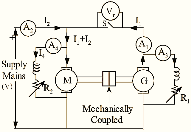
Hopkinson’s Test requires two machines which are identical. The test can be carried out at full-load on the two identical machines. The two machines are mechanically coupled and are electrically adjusted so that, one of them acts as a motor and other as generator. The motor supplies the mechanical power which is utilized to drive the generator. while generator develops electrical power to be utilized in driving the motor. In the absence of losses, the machines will run without any external power supply. But due to the losses, output of generator is not enough to drive the motor and vice-versa. These losses are supplied from supply mains. Hence, in this test the power drawn from the supply mains will be required to overcome the internal losses of two machines. The connections for conducting Hopkinson’s test are as shown in figure 1.
Machine M is started as a motor and supply is given by means of a starter. The main switch of other machine is kept open and the motor is made to run at its normal speed with the help of its shunt regulator. Machine ‘M’ drives machine ‘G’ as a generator. The voltage of ‘G’ is adjusted with the help of its field regulator till voltmeter V1 reads zero. This shows that, the voltage is same as supply mains both in polarity and magnitude.
Now, the switch ‘S’ is closed. Let, the readings of ammeters A1, A2, A3 and A4 connected in the circuit measure the current supplied by generator as I1, line current as I2, generator field current as I3 and motor field current as I4 respectively.
If V is supply voltage then,
Motor input,
PM = V(I1 + I2)
Generator output,
PG = VI1
Assuming that both machines have same efficiency (η).
Output of motor = Efficiency × motor Input
= η × V(I1 + I2) = Generator input
Generator output = η × Generator input
= η × η × V (I1 + I2)…(2)
From equations (1) and (2),
VI1 = η2 V (I1 + I2)
\[V{{I}_{1}}={{\eta }^{2}}V({{I}_{1}}+{{I}_{2}})\]
Let,
Resistance of armature of each machine = Ra
Armature copper loss in generator = (I1 + I3)2 Ra
Armature copper loss in motor = (I1 + I2 – I4)2 Ra
Shunt copper loss in generator = VI3
Shunt copper loss in motor = VI4
Total copper loss = (I1 + I3)2 Ra + (I1 + I2 – I4)2 Ra + VI3 + VI4
Total losses of both machines = Power drawn from supply = VI2
If the total copper loss is subtracted from total losses, then the stray loss for the motor generator set can be obtained.
Total Stray loss, PS(T) = VI2 – [(I1 + I3)2 Ra + (I1 + I2 – I4)2 Ra + VI3 + VI4]
And, Stray loss of each machine,
\[{{P}_{S}}=\frac{{{P}_{S}}(T)}{2}\]
Efficiency of Motor
Motor input,
PM = V(I1 + I2)
Total loss,
PL(M) = Armature loss + Field loss + Stray loss
= (I1 + I2 – I4)2 Ra + VI4 + PS
Motor output = V(I1 + I2) – PL(M)
\[{{\eta }_{M}}=\frac{V({{I}_{1}}+{{I}_{2}})-{{P}_{L(M)}}}{V({{I}_{1}}+{{I}_{2}})}\]
Efficiency of Generator
Generator output,
PG = VI1
Total losses,
PL(G) = Armature loss + Field loss + Stray loss
= (I1 + I3)2 Ra + VI3 + PS
Generator input = VI1 + PL(G)
\[{{\eta }_{G}}=\frac{V{{I}_{1}}}{V{{I}_{1}}+{{P}_{L(G)}}}\times 100\]
Advantages of Hopkinson’s Test :
- This test is performed on full-load conditions. Therefore, any change in temperature rise and quality of commutations of the two identical machines can be noticed.
- Due to full load condition, the variation in iron loss because of flux distortion is considered.
- The power requirement for this test is less in comparison to full load powers of both the machines.
Disadvantages of Hopkinson’s Test :
- Availability of two identical machines is difficult.
- The iron losses of the two machines are different due to different excitation and they cannot be separated.
- In case of small machines the loads on machines are not equal, this may cause difficulty in analysis.